Switching stress dictates mercury contact longevity. Turn-on inrush current frequently dwarfs steady-state running current, while turn-off inductive kicks generate steep voltage transients that accelerate electrode and envelope degradation.
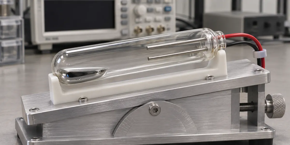
This guide focuses specifically on mercury tilt switches, where liquid mercury pools and bridges electrodes through physical angular displacement. These devices differ mechanically and thermally from mercury-wetted reed relays or heavy-duty displacement relays; published ratings and service life figures from those devices do not apply here.
What Determines Mercury Switch Contact Life?
Actual service life depends on three core variables: switched electrical load, internal construction, and real-world operating conditions. Mechanical endurance or unloaded cycle ratings provide little guidance on real-world longevity under power. Unlike dry contacts that suffer mechanical pitting and erosion, liquid mercury creates a self-renewing contact interface. Even so, the switch remains bounded by glass-to-metal seal integrity, internal gas pressure, and electrode vaporization limits.
Steady-state current drives thermal rise, but transient turn-on current and turn-off voltage deliver the most severe localized stress. Peak amplitude, pulse duration, and cycling frequency dictate whether arc energy vaporizes mercury or fouls the fill gas. For mercury tilt switches, mounting angle and movement speed also govern contact make-and-break positions. Any meaningful life assessment must replicate the actual mechanical sweep alongside operating temperatures.

How Different Load Types Affect Contact Life
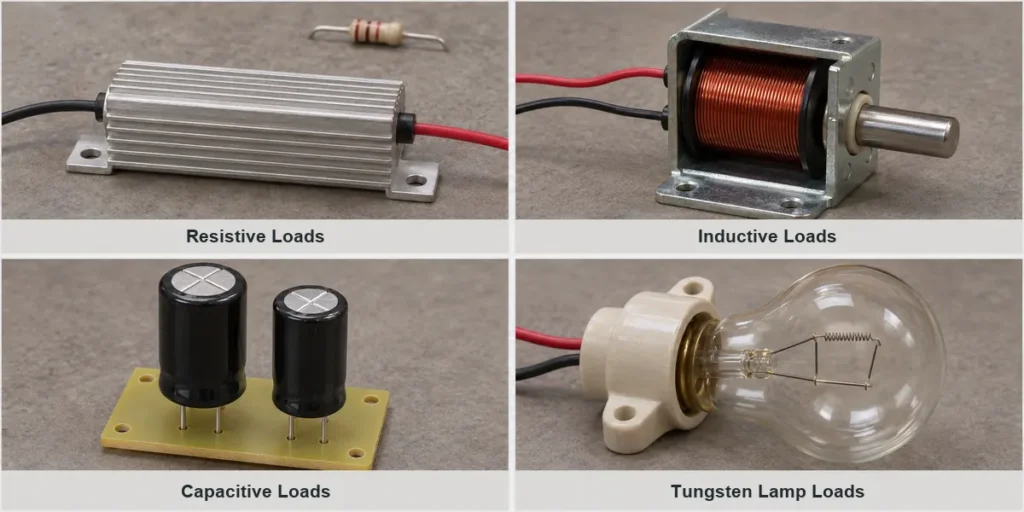
Electrical loads rarely present pure characteristics; most circuits combine resistive, inductive, and capacitive behaviors. Each profile affects the mercury pool differently during make and break events.
Resistive Loads
A stable resistive load serves as the baseline for published switching ratings. Current follows applied voltage and circuit resistance directly, producing no stored magnetic energy or capacitive charging surges. Heating elements demand extra scrutiny: cold resistance measures significantly lower than operational resistance at temperature, generating an initial current step at turn-on. Confirm ratings against both initial cold current and stabilized hot current.
Inductive Loads
Inductive components store magnetic energy in their coils. When the mercury pool breaks contact, collapsing flux generates high-voltage inductive transients that sustain arcs across the opening gap. Motors and transformers introduce heavy starting currents, while DC solenoids present extended current rise times. Consequently, a pure resistive rating cannot qualify a switch for direct motor or coil switching. Always verify both the startup current profile and turn-off peak voltage before specifying a switch.
Capacitive Loads
Connecting a discharged capacitor to a voltage source draws an instantaneous charging current limited only by circuit loop impedance. Power supplies, filter networks, and distributed cable capacitance all exhibit this behavior. An RMS or average-current meter will miss this microsecond-scale surge entirely. Measure peak current amplitude and pulse duration with high-bandwidth equipment to confirm the pulse remains within switch limits.
Tungsten Lamp Loads
A cold tungsten filament has far lower resistance than a hot filament, creating a substantial current surge until thermal equilibrium is reached. Frequent cycling repeatedly exposes the electrodes to this peak stress. Select switches based on cold-start inrush rather than nominal lamp wattage. LED drivers behave quite differently: their inrush originates from input filter capacitors, requiring capacitive rather than filament analysis.
| Load Type | Typical Switching Stress | What to Verify |
| Resistive loads | Continuous current and heating | Highest operating current and cold resistance |
| Inductive loads | Turn-off voltage; possible starting surge | Startup current, opening voltage, and suppression |
| Capacitive loads | Charging pulse at closure | Peak current, pulse duration, and circuit impedance |
| Tungsten lamp loads | Cold-filament inrush | Cold-start current and switching frequency |
These checks define load demands, which must then align with the switch’s documented operational limits.
How to Read Mercury Switch Load Ratings
Datasheet ratings must be evaluated simultaneously. Meeting a voltage limit does not relax a current constraint, and staying under maximum wattage does not permit exceeding either parameter.
Electrical Limits
For resistive loads, calculate total volt-amperes or watts (voltage multiplied by current) and compare it against maximum switching capacity. Operating below rated voltage never permits exceeding the maximum continuous or switching current. Additionally, open-contact dielectric withstand voltage must not be confused with active switching voltage. A device rated to isolate high voltages across open contacts rarely tolerates breaking an active circuit at that same potential.
Carry Current and Switching Current
Carry current and switching current define two distinct operational boundaries. Carry current applies only after the mercury pool has settled across the electrodes. Switching current defines the maximum load the contacts can dynamically make or break without damaging arc energy. A higher continuous carry rating never justifies an equivalent current during contact closure. If a datasheet quotes only switching capacity, treat that figure as the absolute limit for both states.
Load Compatibility
AC ratings do not translate directly to DC circuits. AC waveforms pass through zero voltage every half-cycle, naturally quenching arcs across opening contacts. DC circuits lack this periodic zero-crossing, allowing arcs to persist longer and burn hotter. Direct inductive, motor, or lamp control requires explicit manufacturer ratings. Applying an arbitrary conversion factor to derate AC resistive values for DC inductive loads introduces significant reliability risks.
Electrical Life Test Conditions
Cycle life figures are valid only under the specific test parameters documented by the manufacturer: voltage, current, power factor, cycle rate, ambient temperature, and tilt angle. A switch rated for high cycles under a light resistive signal will degrade rapidly if exposed to repeated capacitive charging surges or unsuppressed inductive spikes.
How to Reduce Switching Stress
Mitigating electrical stress at the source preserves contact integrity. When direct switching exceeds contact ratings, external suppression or intermediate power staging via solid state relays isolates the tilt switch from damaging transients.
Limit Turn-On Inrush
Capacitive DC circuits benefit from active soft-start stages, NTC thermistors, or dedicated pre-charge paths. Upstream power supplies with soft-start functionality only protect against initial mains power-up; if the tilt switch downstream repeatedly connects a discharged capacitive load to a live rail, full inrush occurs at every tilt event. Fixed series resistors offer a passive alternative when continuous voltage drop and dissipation remain tolerable. Size the resistor for cumulative pulse energy, and confirm that minimum operating voltage remains available at the load.
Suppress Turn-Off Transients
Stored inductive energy requires a dedicated discharge loop to prevent sustained arcing during contact separation. For DC coils, a flyback diode placed anti-parallel across the load provides a recirculation path for decaying current, though it slightly extends mechanical dropout time.
For AC loads, fit a tuned RC snubber network or metal-oxide varistor (MOV) sized to clamp voltage peaks below the switch withstand rating. Never place an unresisted capacitor directly across the switch contacts: stored charge discharges directly through the mercury pool upon re-closure, trading a turn-off voltage spike for a severe turn-on current surge.

Offload Power Switching
Using the tilt switch as a low-power pilot device protects the physical mechanism from heavy currents. An electromechanical contactor or solid-state switch handles the primary load while the tilt switch carries only milliamps of control signal. Even in pilot duty, ensure the pilot circuit itself respects switch ratings. An electromechanical relay coil represents an inductive load that requires its own diode or snubber.
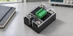
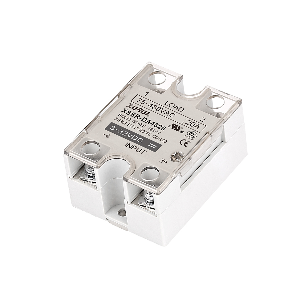
For AC loads, the XSSR-W6 solid state relay series illustrates optical isolation between pilot logic and high-current power switching. Select the SSR based on required surge withstand, load voltage, and thermal heatsinking. Keep in mind that adding an SSR offloads the switch, but the SSR itself must still handle load inrush.

How to Validate Contact Life in Your Application
Empirical testing verifies that transient voltages, inrush currents, and physical cycling remain within design margins across the expected service life. Define target cycle thresholds and pass/fail criteria before testing.
Measure Switching Transients
Capture contact closure current and opening voltage with an oscilloscope and appropriately rated current and differential voltage probes. Standard multimeters read average or RMS values, completely missing sub-millisecond inrush spikes and microsecond inductive kickback. Capture worst-case operational states, such as cold-filament startups, discharged filter capacitors, and maximum operating temperatures. Measure peak amplitude, duration, and ringing frequency to confirm compliance with switch specifications.

Run Representative Life Tests
Cycle sample switches under actual load, protection, and mechanical actuation conditions. Establish cycle targets based on the equipment warranty or service lifetime. Match the test frequency, mechanical tilt speed, angular excursion, and ambient temperature to the end application. Avoid over-accelerating test cycle rates. Artificial cycling speeds prevent normal thermal dissipation, alter mercury surface tension recovery, and mask real-world degradation patterns.
Check Contact Performance
Monitor contact performance continuously rather than relying on an end-of-test continuity check. Track parameters such as contact resistance drift, open-circuit leakage, and actuation angle shift.

For application assistance or power-stage sizing, discuss operating conditions with XURUI. Providing the switch part number, load voltage, peak and steady-state currents, cycle frequency, and thermal environment ensures an accurate engineering evaluation.
External Sources
- FDA: Electronic Relays
- TE Connectivity: Relay Contact Life: Materials, Ratings, and Styles
- Standex Detect: Handling and Load Precautions
- Pickering Electronics: Understanding Reed Relay Specifications
- Panasonic Industry: Relays Cautions for Use
- Texas Instruments: Managing Inrush Current