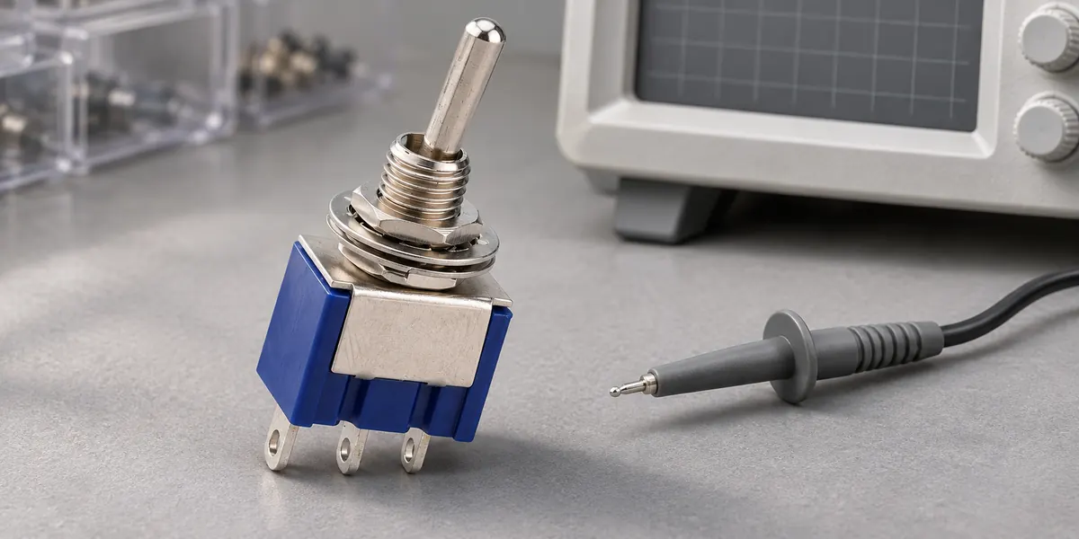
A make-before-break switch closes the next circuit path before disconnecting the existing one, creating a brief overlap. A break-before-make switch disconnects the active path before closing the next, creating a momentary open interval. Selecting between the two determines whether a circuit experiences a transient short between poles or an open-circuit dead time during actuation.
This guide examines mechanical changeover contacts and the circuit constraints that dictate their selection. While solid-state analog switches deal with similar transition requirements, their timing characteristics differ fundamentally from mechanical contact assemblies.
What Is the Difference Between Make-Before-Break and Break-Before-Make?
The fundamental difference lies in contact sequencing during the transition window. While schematic conventions such as a toggle switch symbol depict basic pole and throw arrangements, standard schematic symbols rarely convey whether contacts short or isolate during transfer.
Make-Before-Break Contacts
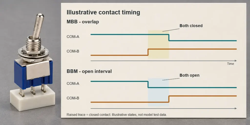
Make-before-break (MBB) mechanisms close the approaching contact before releasing the active one. During transfer from position A to position B, the common terminal (COM) transitions from A, passes through a momentary state where it bridges both A and B simultaneously, and settles on B. Industry terminology designates this as shorting action.
This intentional overlap preserves continuous conduction throughout the stroke. Operating this mechanism safely requires the attached circuitry to withstand the temporary parallel connection between contacts A and B.
Break-Before-Make Contacts
Break-before-make (BBM) mechanisms break the initial connection prior to establishing the new one. In the same A-to-B transfer, COM releases contact A, enters an open state isolated from both terminals, and engages contact B. This sequence represents non-shorting action.
The open state ensures complete isolation between incoming circuits, preventing cross-conduction. The table below outlines core transition characteristics. Specific transfer durations depend on switch geometry and actuation speed.
| Comparison Point | Make-Before-Break Switch | Break-Before-Make Switch |
| Contact sequence | New path closes before old path opens | Old path opens before new path closes |
| Transition state | Both paths briefly connected | Both paths briefly disconnected |
| Common term | Shorting | Non-shorting |
| Continuity | Designed to maintain a conducting path | Includes an open interval |
| Circuit requirement | Must tolerate overlap | Must tolerate interruption |
| Timing specification | Verify overlap under stated conditions | Verify open interval under stated conditions |
How Contact Timing Affects Shorts and Signal Dropouts
Whether a transition causes a system fault depends on how downstream loads and upstream sources react to momentary bridging or temporary isolation.
Contact Overlap
Contact overlap establishes a temporary conductive bridge between the switched terminals. When these terminals connect to independent voltage rails or mismatched energy sources, cross-current flows across the bridge. With low contact resistance, even microsecond-range overlaps can produce destructive inrush currents that pit contact surfaces or trip upstream protection.
In circuits tailored for shorting action, this bridge prevents floating nodes or interrupted current paths. BBM mechanisms eliminate intentional bridging, yet system designers must note that BBM switches cannot guard against external shorts caused by contact welding, excessive arcing, or wiring errors.
Open-Circuit Intervals
An open interval completely decouples the source from the load during the physical stroke. The vulnerability of the system depends on input impedance and downstream filtering. Unbiased high-impedance inputs will float into undefined logic levels, picking up radiated EMI. In contrast, well-filtered or capacitive loads maintain regulated rail voltages across typical transfer windows.
Mechanical contact bounce must be evaluated independently from transfer timing. Bounce occurs when elastic impact forces contacts to oscillate open and closed upon touchdown. Specifying an MBB switch guarantees continuity across the transfer, but contact bounce can still introduce transient interruptions on the engaged terminal.
Which Contact Timing Fits Your Application?
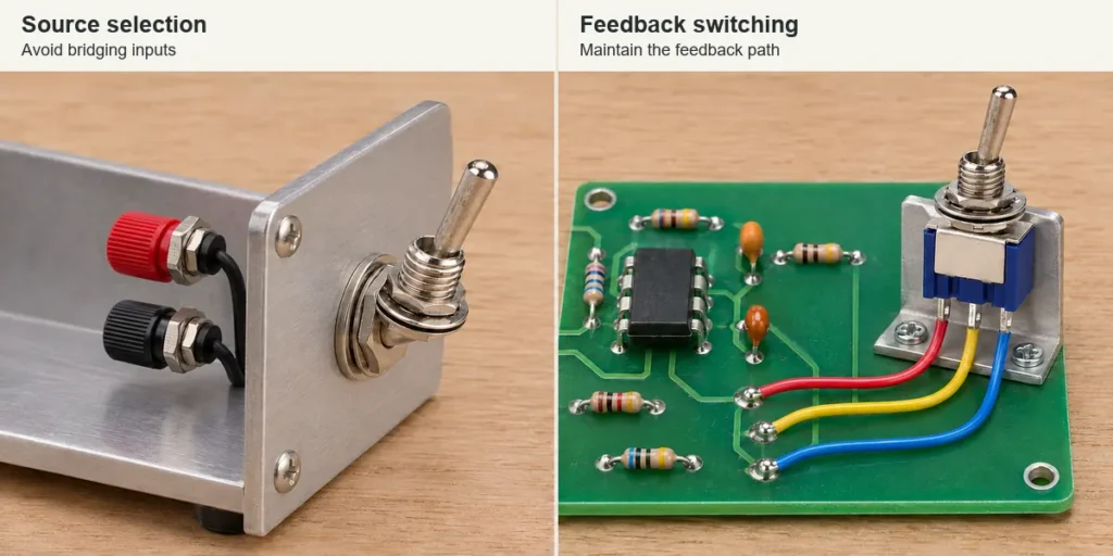
Application requirements center on a single rule: select BBM when independent inputs must remain strictly isolated, and select MBB when an uninterrupted current or feedback path is mandatory.
Power Source Selection
Selecting between multiple power feeds (such as mains and generator supplies or dual DC rails) requires BBM contacts as the default topology to prevent cross-feeding sources. When critical loads demand continuous power through the transfer, bridge the dead time with holdup capacitors, battery-backed rails, or dedicated OR-ing diodes rather than substituting an MBB switch. Forcing MBB contacts into multi-source switching creates a direct phase-to-phase or rail-to-rail fault.
Switches featuring a center-OFF position offer a stable isolated state, yet mechanical travel characteristics between detents must still be confirmed. Consult the ON-OFF-ON wiring guide to align terminal contact mapping with source-selection layouts.
Measurement Range Switching
Instrument range selection frequently mandates MBB contacts to maintain closed-loop safety. Current transformer (CT) secondary test circuits represent the most critical example. Opening a CT secondary circuit while the primary is energized induces destructive, high-voltage spikes across the open terminals. Specialized MBB rotary or selector switches bridge shunt resistances during range steps, ensuring the secondary loop remains loaded. Conversely, multi-channel voltage telemetry demands BBM configurations. Bridging voltage taps would short adjacent sense lines, skewing measurement data and risking instrument damage.
Audio Switching
Audio routing systems rely on BBM switches to toggle between line-level sources, preventing output stage contention between components. Audible pops and thumps typically stem from DC offset differences across contacts rather than contact mechanical timing alone. Complete suppression often requires active muting relays, pull-down bleeding resistors, or AC-coupling capacitors alongside BBM hardware.
Operational amplifier feedback networks invert this requirement. Stepping through gain ranges via feedback resistor selection benefits from MBB switching. An open-circuit interval removes loop feedback entirely, driving the op-amp output into supply rail saturation. MBB contacts temporarily parallel the two gain resistors, keeping the amplifier linear during the switch transition.
Control Signal Switching
Digital logic inputs and PLC control lines require BBM configurations whenever simultaneous high signals trigger conflicting interlocks or indeterminate logic states. Review controller input impedance, debounce filtering, and pull-up/pull-down networks. Proper biasing ensures the brief BBM open interval reads predictably as an inactive state, whereas excessive RC filter delays might mask rapid switching events. When specifying panel-mounted toggle switches, verify that the mechanical pole-and-throw configuration matches the logic schema before finalizing the contact sequence specification.
How to Verify Contact Timing Before Selecting a Switch
Static bench checks with a digital multimeter confirm resting states, but they cannot capture microsecond transition windows or verify contact sequencing during travel. Validation requires systematic specification, datasheet verification, and dynamic testing.
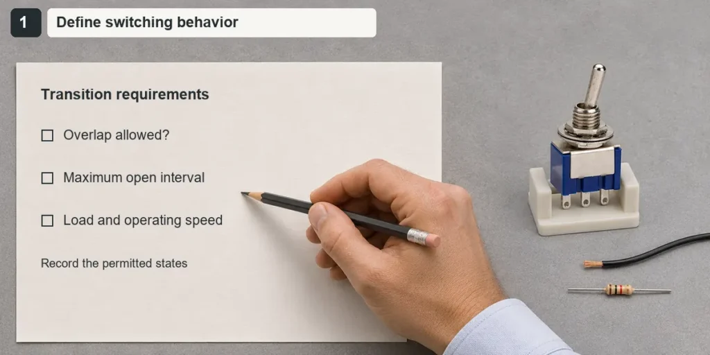
Step1: Define the Required Switching Behavior
Establish explicit operational boundaries based on circuit tolerances:
- Confirm whether switched terminals can safely tolerate momentary cross-connection.
- Establish the maximum tolerable open-circuit dead time, or the mandatory minimum overlap duration.
- Define operating voltage and current levels, accounting for reactive transients and motor/lamp inrush.
- Document bidirectional actuation speeds and expected mechanical operator profiles.
Mechanical mechanism types significantly influence timing repeatability. As detailed in the comparison of snap-action and slow-action switches, internal spring triggers produce high-speed contact transfer largely independent of user actuation speed, whereas slow-action designs track toggle velocity directly.
If an application permits neither overlap nor dead time, standard mechanical changeover switches are unsuitable. Such systems require solid-state commutation, active diode-OR arrangements, or capacitive energy buffers.
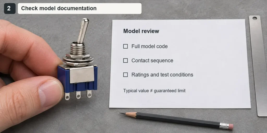
Step2: Check the Exact Model Documentation
Confirm explicit MBB, BBM, shorting, or non-shorting designations tied to the complete orderable part number and suffix code. Basic contact tables document terminal connectivity in settled detents, whereas contact-travel diagrams reveal physical overlap or separation throughout the stroke. Note that travel distance specifications reflect mechanical displacement rather than time duration.
Review published timing limits under specified test loads. Typical values reflect nominal factory averages; designs should be calculated against guaranteed minimum or maximum parameters. Always verify voltage and current ratings against steady-state and inrush parameters. Correct sequencing cannot protect contacts mismatched to the electrical load.
Series catalog entries like the XT Series toggle switch display pole, throw, and mounting hardware options. Confirm that the exact sub-tier suffix denotes the required contact sequence before issuing procurement specifications.
Step3: Verify the Switching Sequence
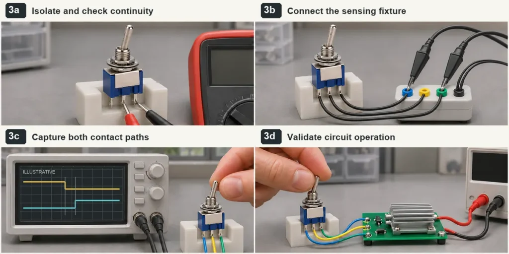
Isolate the unpowered switch from external hardware and confirm resting continuity across terminals. For dynamic verification, configure a low-voltage, current-limited pull-up test rig suited to the contact plating material. Connect both switched paths to an oscilloscope running on a shared timebase. When using standard single-ended probes, tie ground leads to a single common circuit reference. If switched channels do not share ground, utilize differential probes or galvanically isolated scope channels to prevent ground-loop shorts.
Capture the transition trace to evaluate:
- Simultaneous conduction on both channels (MBB overlap).
- Simultaneous high-impedance state across both channels (BBM dead time).
- Contact bounce duration and re-strike events upon arrival.
Execute tests across multiple cycles in both directions, applying both minimum and maximum expected toggle speeds. On multi-pole variants, monitor inter-pole skew to detect non-synchronized contact engagement. Note that a clean voltage output trace on a populated PCB does not guarantee contact continuity; downstream decoupling capacitors frequently mask brief open intervals. Conclude sequence testing with full-load functional validation.
For assistance in verifying specific contact ratings, submit your switching requirements to XURUI alongside your circuit topology, load ratings, permitted transfer margins, and target part numbers for technical review.
External Sources
- Carling Technologies: Contacts and Contact Functions
- Analog Devices: Break-Before-Make Definition
- Toshiba: What Is a Break-Before-Make Circuit?
- Analog Devices: Selecting the Right CMOS Analog Switch
- Megger: BA-185 Current Transformer Burden Ammeter
- OMRON: Basic Switches and Contact Switching Time