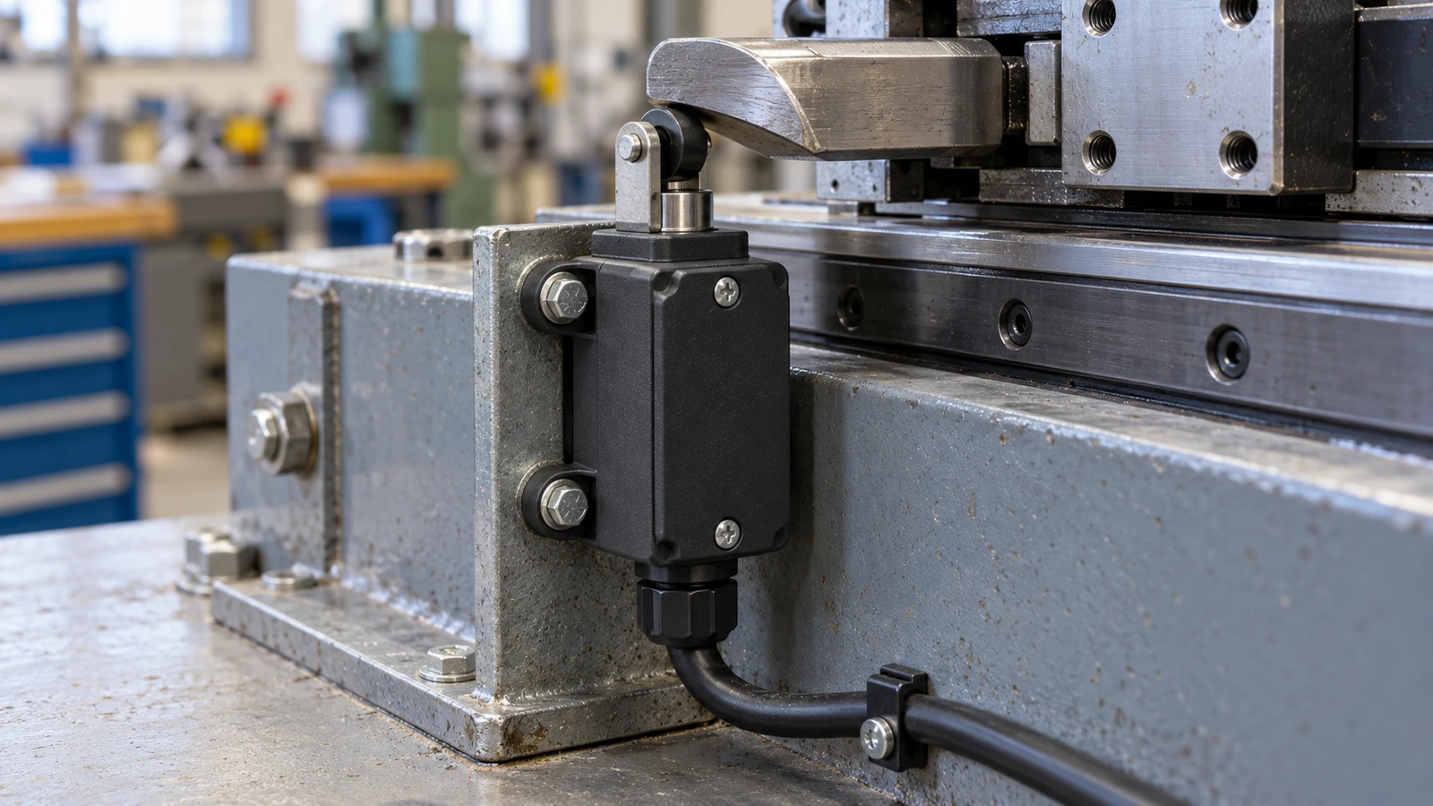
For slow-moving mechanisms, engineers frequently select snap-action switches due to contact transfer occurring independently of actuator velocity. Conversely, slow-action switches excel where synchronous, repeatable contact sequencing is mandatory. Neither mechanism offers universal longevity or inherent safety advantages; matching the device to the application requires evaluating actual electrical loads, travel kinematics, and functional safety architecture.
Key Differences Between Snap-Action and Slow-Action Switches
Selecting between these two architectures starts with evaluating how actuator displacement translates into contact separation under operational loads.
| Comparison Point | Snap-Action | Slow-Action |
| Contact movement | Stored spring energy drives instantaneous transfer | Contact displacement tracks actuator position directly |
| Actuation speed | Contact transfer velocity is independent of actuator speed | Contact velocity matches actuator displacement rate directly |
| Operating and release points | Separated by inherent differential travel (hysteresis) | Negligible differential travel; contacts reset during initial return stroke |
| Slow mechanical inputs | Robust; prevents contact hovering, teasing, and chattering | Demands compliance with manufacturer minimum actuation speed limits |
| Contact sequencing | Fixed by internal spring and contact blade geometry | Highly configurable, supporting overlapping (make-before-break) setups |
| Service life | Dictated by mechanical fatigue limits, electrical load, and duty cycle | Dictated by mechanical fatigue limits, electrical load, and duty cycle |
| Safety suitability | Positive opening (direct drive) available on certified units | Positive opening (direct drive) available on certified units |
How the Two Switching Mechanisms Work
Internal mechanical kinematics govern contact velocity and dictate how physical force transfers from the actuator to the contact faces.
Snap-Action
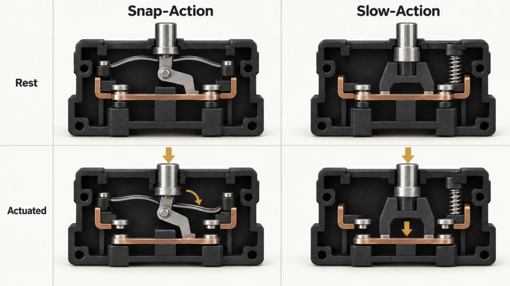
A snap-action switch uses an over-center spring design to store mechanical energy during actuator travel. When the operating point is reached, the tension spring snaps over, throwing the movable contact across the gap within milliseconds. Actuator speed does not govern transfer velocity, which prevents arc hovering.
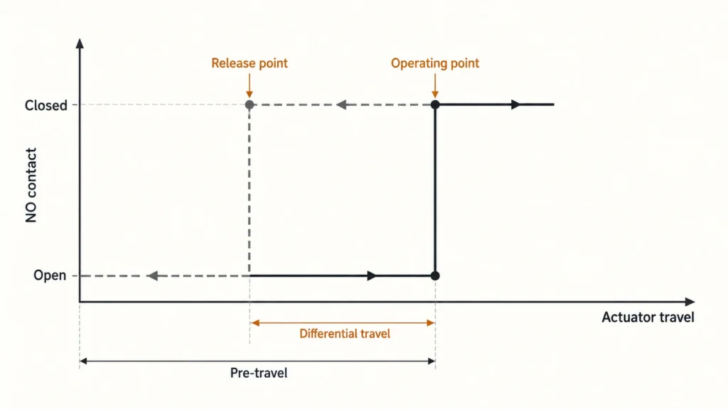
Examining the internal snap-action mechanism of a micro switch reveals how leaf-spring tension controls this rapid snap. On the return stroke, the mechanism resets only after the plunger retracts past a distinct release point. Accommodating this deadband, known as hysteresis, is mandatory when profiling cams, positioning trip dogs, or setting mechanical travel stops.
Slow-Action
A slow-action switch couples contact travel directly to actuator displacement. Contacts open and close in lockstep with external physical movement: drive the plunger slowly, and the contacts separate at that exact velocity. Manufacturer datasheets designate this as slow-make, slow-break operation.
This design produces discrete digital states rather than variable outputs. Contact travel diagrams define the exact displacement thresholds where normally closed (NC) contacts break and normally open (NO) contacts make. This direct kinematic relationship gives machine designers precise mechanical control over contact switching points.
What Switching Speed Means in Practice
Effective switching response depends on overall cycle latency and arc mitigation rather than contact transfer speed alone.
While switching speed describes contact flight time between terminals, actual loop latency includes the mechanical pre-travel required to reach the trip point. A fast-snapping unit with excessive pre-travel often signals later than a slow-action unit with a tight operating stroke.
Contact transfer speed primarily serves to suppress contact teasing:
- The creeping cam issue: When an operating cam approaches a slow-action switch at low velocity and stalls near the trip point, contacts hover at the separation threshold. Under electrical load, this condition triggers contact chatter, electrical noise, or sustained micro-arcing. Actuator drive profiles must never drop below the minimum specified actuation speed.
- The snap-action advantage: Snap-action mechanisms decouple contact velocity from actuator speed, eliminating teasing altogether. However, resetting requires accommodating reset travel. The differential travel and hysteresis of a micro switch dictate the stroke distance required to re-arm the mechanism. Inadequate return travel leaves the mechanism latched, resulting in missed cycles.
How Contact Action Affects Switch Life
Mechanical fatigue and electrical erosion represent distinct degradation pathways that must be isolated during component sizing.
Mechanical Wear
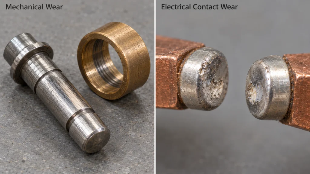
Mechanical wear degrades internal leaf springs, pivots, guide bushings, and roller bearings. Excessive overtravel, off-axis side loading, and shock loads degrade switch mechanisms regardless of contact topology. Using a limit switch plunger as a mechanical hard stop destroys the internal mechanism rapidly, regardless of rated mechanical endurance.
Published mechanical ratings reflect dry cycling under zero electrical current. These figures prove mechanical fatigue limits of the housing and spring alloy, but they reveal nothing about survival under motor, solenoid, or inductive relay loads. Field reliability calculations must evaluate electrical and mechanical endurance as separate metrics.
Electrical Contact Wear
Electrical degradation involves contact vaporization, material transfer, and weld formation during arc events. High-speed contact separation shortens arc duration, yet contact alloy metallurgy, gap clearance, and circuit suppression exert equal influence. Snap-action contacts do not inherently outlast slow-action contacts under heavy electrical duty.
Endurance comparisons require matching operating parameters: operating voltage, continuous load, inrush peaks, and switching frequency. Resistive load ratings (AC-12 or DC-12) do not predict survivability on inductive coils (AC-15 or DC-13), and AC ratings cannot be transposed to DC circuits. Circuits driving reactive loads must include flyback diodes, RC snubbers, or varistors to preserve contact surfaces.
What Makes a Switch Suitable for Safety Applications
Functional safety relies on positive mechanical force and certified direct drive rather than high-speed contact snapping.
Direct Opening
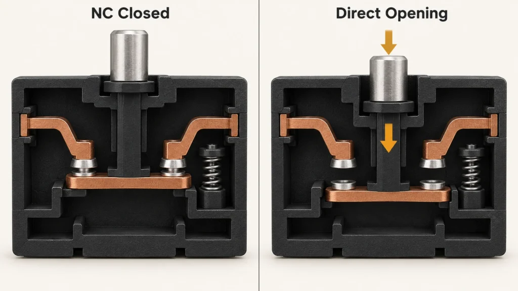
Direct opening, or positive opening operation, applies unyielding mechanical force from the actuator to shear open normally closed (NC) contacts. This mechanism guarantees circuit disconnection even if contact tips weld together, removing dependence on internal return springs. Standardized switches denote this feature with the positive break symbol and define the required stroke and force per EN/IEC 60947-5-1.
Positive opening is available on both snap-action and slow-action switches, as seen across industrial platforms like the OMRON D4N series. An audible snap never guarantees circuit interruption: an internal over-center spring can trip while welded contacts remain bridged. Reliable safety disconnection requires driving the actuator through its full specified direct opening travel (DOT).
Validated Safety Function
A single switch cannot establish safety integrity on its own. Functional safety depends on the complete safety loop, encompassing actuator mounting, dual-channel wiring, safety relays or PLCs, and downstream contactors. Component certification does not substitute for systematic risk reduction.
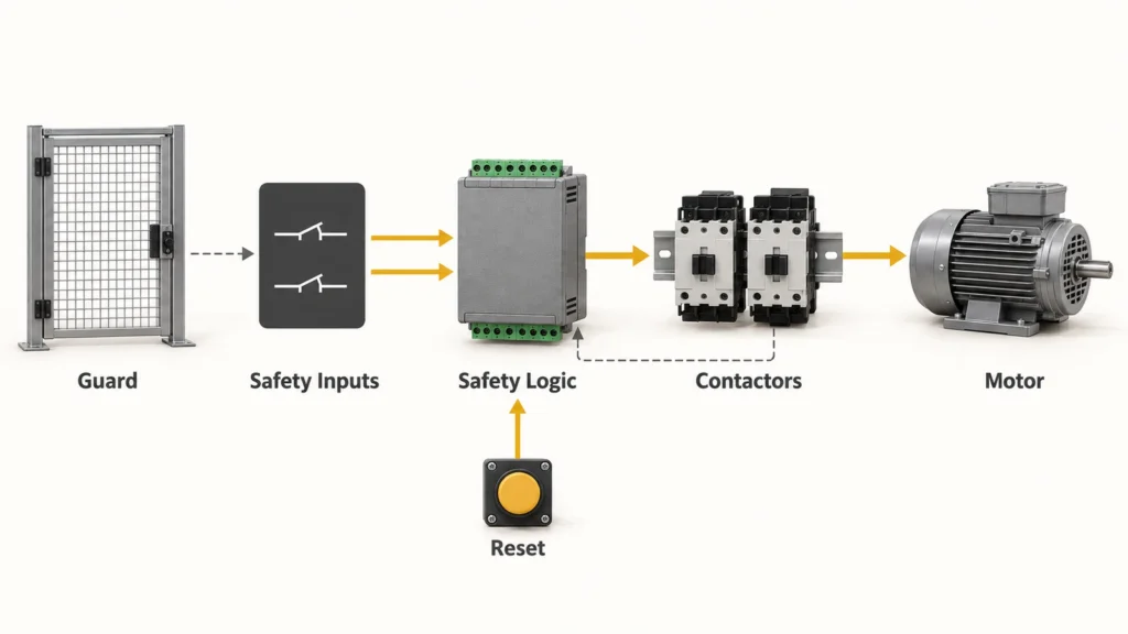
In machine guarding applications, proper safety door switch selection and wiring must address stopping time analysis, defeat resistance, cross-fault monitoring, and restart interlocks. A closed guard contact confirms position only, not the cessation of dangerous motion. Machine builders must validate the overall circuit response against ISO 13849-1 or IEC 62061 risk assessments.
Which Switching Mechanism Fits Your Application
Specifying the appropriate contact action requires aligning physical actuation dynamics, electrical load characteristics, and safety architecture constraints.
Slow Actuation
Creeping or erratic actuation speeds demand snap-action mechanisms. Their internal spring releases instantaneously upon reaching the operating point, suppressing arc formation on slow-feed cams, liquid-level floats, and bimetallic thermal actuators.
Slow-action devices installed on creeping mechanisms inevitably fail due to arcing unless the input velocity strictly exceeds the manufacturer minimum actuation threshold. Conversely, snap-action switches impose reset travel limitations. Designers must benchmark minimum approach velocity, total stroke, and available return travel prior to hardware selection.
Contact Sequencing
Contact sequencing defines the switching relationship between distinct poles during actuator displacement:
- Break-Before-Make (BBM): Enforces a dead-time interval where both circuits remain open simultaneously.
- Make-Before-Break (MBB): Provides an intentional overlap where the incoming circuit closes before the outgoing circuit breaks.
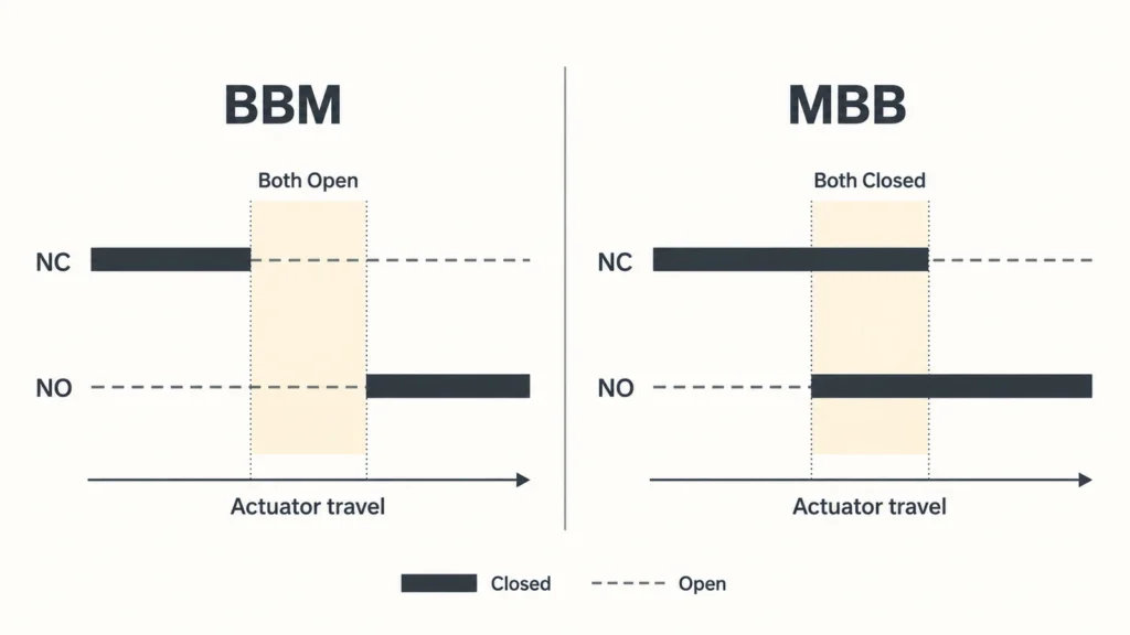
Applications requiring overlapping contacts, such as transferring signal state without dropping control power, rely almost exclusively on slow-action mechanisms like those found in OMRON D4N contact blocks. Designers must consult contact stroke diagrams rather than relying on part numbering conventions. Unintended contact overlap can short power rails or disrupt ladder logic even when replacement hardware fits existing mounting footprints.
Safety Interlocking
Safety interlocks must meet the performance level (PLr) or safety integrity level (SIL) defined by the machine risk assessment. Determining contact action follows the safety loop design. Repurposing standard position limit switches as safety interlocks introduces critical compliance risks, even if fitted with replacement contact blocks.
For retrofits involving altered travel profiles or specialized contact timing, request a model and application review from XURUI to verify stroke curves, contact diagrams, and electrical ratings against proposed mechanical drawings. Final safety validation and documentation remain the responsibility of the machine builder.
Engineering selection workflow:
- Audit mechanical kinematics: Quantify approach speed, total travel, return stroke margin, and mounting rigidity.
- Verify electrical parameters: Check contact sequencing, inrush and steady-state currents, dry-circuit thresholds, and snubbing provisions.
- Validate field performance: Measure physical trip and reset clearances on the machine, then test direct opening function under full system load.
Frequently Asked Questions
Are Snap-Action and Slow-Action Switches Interchangeable?
Rarely, and never without detailed stroke verification. Even if two switches share identical housing dimensions and mounting hole centers, changing mechanism types alters operating positions, reset travel, contact sequencing, and minimum velocity limits. In safety circuits, swapping mechanisms without re-profiling the actuating cam can prevent the mechanism from reaching its mandatory positive opening travel distance.
Which Switch Is Suitable for Low-Current Signals?
For low-current signals and dry-circuit logic, contact metallurgy matters far more than actuation kinematics. Standard silver alloy contacts depend on switching arc energy to break down surface oxides, resulting in high contact resistance at low DC voltages and milliamp current levels. PLC and digital inputs demand bifurcated crossbar or gold-flashed contacts. Reviewing how micro switch contact materials affect contact resistance helps prevent intermittent logic errors in low-energy loops.
Is a Toggle Switch a Snap-Action Switch?
Not necessarily. The term toggle designates the external actuator interface, such as a bat handle or lever, while snap action defines the internal over-center spring topology. Many toggle switches incorporate internal spring blades for tactile feedback and fast transfer, but others employ slow-make, slow-break sliding wipers. Always verify internal contact kinematics in the technical datasheet when switching inductive or low-voltage circuits.
References & Authoritative Sources
- Schneider Electric Technical FAQ on Snap Action and Slow Break Contacts
- Panasonic Industry Micro Switch Technical Terminology and Cautions for Use
- OMRON D4N Safety Limit Switch Technical Datasheet