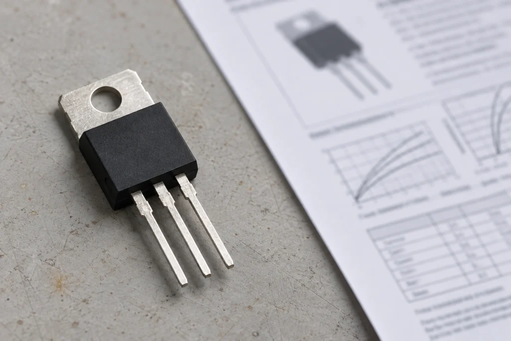
A TRIAC (“triode for alternating current”) is a three-terminal semiconductor switch that conducts current in either direction when triggered. Inside a TRIAC-output solid state relay (SSR), it switches AC load current without moving contacts.
Although SSRs are built with several different output technologies, a standard optically isolated TRIAC-output AC relay illustrates the core switching mechanics: how the TRIAC stage dictates conduction timing, why turn-off is delayed, and what limits reliable operation.
TRIAC symbol and terminals
The TRIAC schematic symbol shows two main load terminals and one control terminal:
- MT1 (A1): The reference terminal for the gate drive circuit.
- MT2 (A2): The opposite end of the main load-current path.
- G (Gate): The control terminal that receives the triggering current.
While the symbol indicates bidirectional switching, it does not imply a universal package pinout. MT1 and MT2 are not interchangeable relative to the gate circuit, so always check the part number’s datasheet before assigning physical leads.
How a TRIAC switches AC power
A TRIAC controls both halves of an AC waveform by turning on at a gate trigger and turning off when main current drops near zero. Gate triggering, latching, and turn-off are separate events within each half-cycle.
Gate-triggered turn-on and latching
A current pulse at the gate starts conduction between MT1 and MT2. The required trigger current (IGT) depends on the specific device and operating conditions, including polarity and junction temperature. Once triggered, the main current must rise above the latching current (IL) before gate drive is removed. As long as current clears that threshold, the TRIAC stays on without continuous gate current.
However, latching only holds the device on for a single half-cycle. After the AC waveform crosses zero and turns the TRIAC off, the drive circuit must re-trigger the gate for the next half-cycle.
Current-zero turn-off
A conducting TRIAC turns off only when its main current falls below the holding current (IH) long enough for the device to recover its blocking state. In an AC circuit, this naturally happens near the current zero crossing. Removing gate drive alone will not interrupt substantial load current that is already flowing; IL governs how conduction is established, while IH governs how it is maintained.
With reactive loads, current zero and voltage zero do not happen at the same time. In an inductive circuit, current continues to flow after the supply voltage crosses zero. Steady DC lacks these periodic zero crossings altogether, preventing a conventional TRIAC output from turning off a continuous DC load on command.
Is a TRIAC the same as a solid state relay?
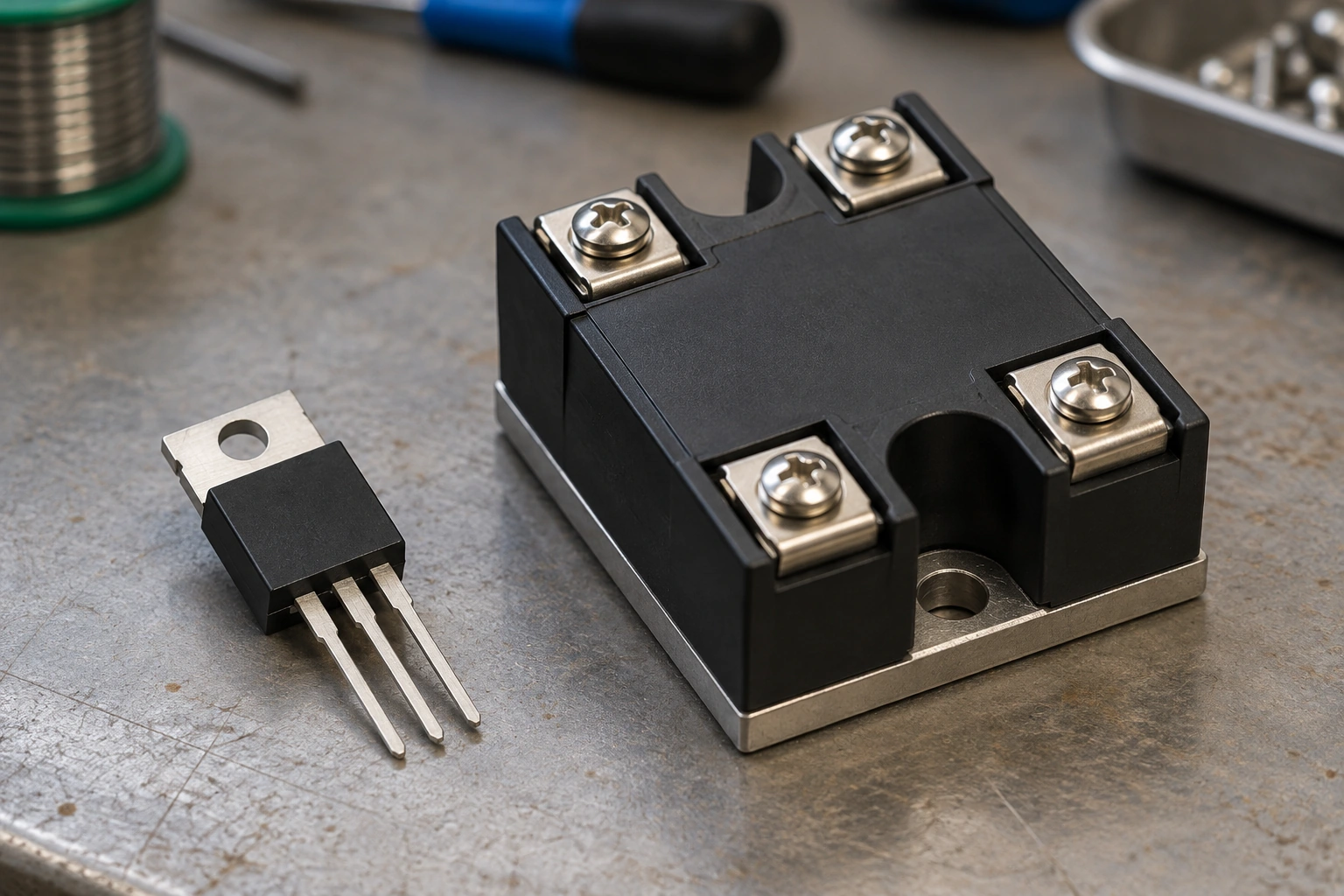
No. A TRIAC is an individual switching component, whereas an SSR combines an input interface, isolation stage, and output switch into a complete relay assembly.
| Comparison Point | Discrete TRIAC | TRIAC-Output SSR |
| Function | Switches current through its main terminals | Accepts a control command and switches a load |
| Drive | Requires an external gate trigger circuit | Provides an input interface and internal gate drive |
| Isolation | Does not inherently isolate gate from load | Often includes optical isolation (verify per datasheet) |
| Integration | Supporting components are designed separately | Packages the drive and output stage together |
| Best fit | Custom equipment or PCB-level design | Equipment requiring a standard relay interface |
Commercial solid state relays also use output switches other than TRIACs. Higher-current AC SSRs often pair two SCRs in inverse-parallel (back-to-back) to handle heavier thermal and commutation demands. Other designs use MOSFETs, whose gate drive can turn the load off at any time without waiting for a current zero crossing. Back-to-back MOSFET topologies can switch both AC and DC loads.
How a TRIAC works inside a solid state relay
In a standard optically isolated SSR, the low-voltage control input activates a light-sensitive driver that triggers the high-voltage power TRIAC. The control signal only manages the trigger timing; the AC line supplies the power to the load.
When the input is energized:
- Input current lights an internal LED.
- Light crosses the isolation barrier to a photosensitive receiver, typically a phototriac driver.
- The phototriac supplies gate current to the main power TRIAC.
- The power TRIAC latches on and conducts load current through the external circuit.
The phototriac driver and the power TRIAC split the workload: the driver handles low-current gate triggering, while the power device carries the main load current. Electrical isolation between the control logic and the AC line comes from the optical coupling stage rather than the bare TRIAC.
When driving a resistive heater, keeping the control input active allows the driver to re-trigger the TRIAC across successive half-cycles. Removing the input signal stops further triggering, and conduction ends at the next current zero crossing.

Zero-cross and random turn-on SSRs
The internal drive circuit determines when the TRIAC can fire relative to the AC waveform. Choosing between zero-cross and random turn-on SSRs comes down to how the load handles inrush current and whether phase-angle control is needed.
Zero-cross
A zero-cross SSR waits to turn on until the AC voltage across its output is near zero. Starting conduction near the voltage zero crossing avoids applying a sudden high-voltage step to resistive loads and keeps switching noise down.
While this works well for standard resistance-heater cycling, it does not guarantee low startup current for every load. Transformers, in particular, can saturate and draw high inrush current when switched at voltage zero. A standard zero-cross relay also cannot be used for phase-angle dimming, as its driver blocks trigger commands mid-cycle.
Random turn-on
A random turn-on SSR begins conduction as soon as the input command arrives, without waiting for voltage zero. Here, “random” simply means the trigger command can occur at any point in the AC waveform, not that the switching time is unpredictable.
This instant response supports phase-angle power control when paired with an external controller that synchronizes with the AC line and selects the exact firing instant. The SSR does not perform dimming on its own, nor does it give the TRIAC the ability to turn off before current zero.
Practical limits of TRIAC switching
TRIAC outputs have strict electrical and thermal boundaries. Treat a datasheet’s current rating as a value tied to specific cooling and load conditions rather than a universal guarantee.
Heat generation
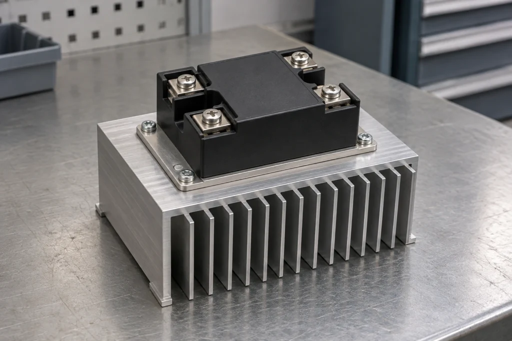
A conducting TRIAC has an on-state voltage drop, so carrying load current continuously generates heat. As current increases, that thermal load must be dissipated outside the enclosure.
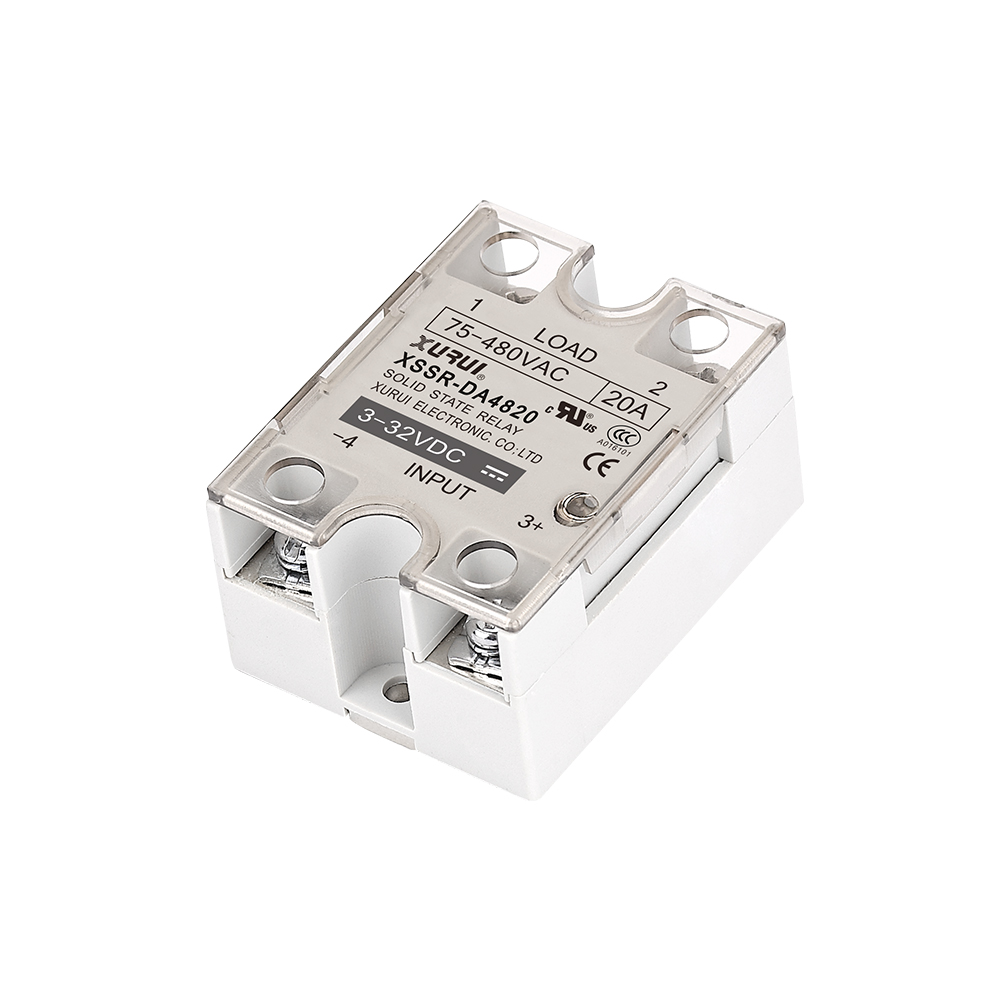
On panel-mounted units like the XSSR-W1 series, usable continuous current depends directly on the heatsink size, airflow, and ambient temperature. Always check the model-specific power dissipation and thermal derating curves to determine the actual allowable load current.
Off-state leakage
Even when turned off, a TRIAC does not provide an open air gap. Small semiconductor leakage remains, and the internal RC snubber network wired across the output adds a capacitive AC leakage path.
This combined off-state leakage current can cause low-power LED loads to glow dimly or trick high-impedance electronic inputs into registering an “on” state. For small loads, compare the relay’s maximum leakage specification at your operating voltage and temperature against the load’s turn-on threshold.
Minimum load requirement
At the low end, a TRIAC-output SSR requires a minimum amount of load current to latch reliably. If the load current is too small, the output may fail to stay on across the half-cycle even when the input LED is lit.
Always evaluate low-power loads against the complete relay’s specified minimum load current. That specification accounts for the internal driver and snubber circuitry, making it distinct from a bare TRIAC’s IL or IH values.
Turn-off issues with inductive loads
Phase lag between current and voltage complicates turn-off in inductive circuits. When load current finally falls to zero and the TRIAC attempts to commutate (turn off), the supply voltage is already partway through its cycle, causing the voltage across the relay output to jump rapidly.
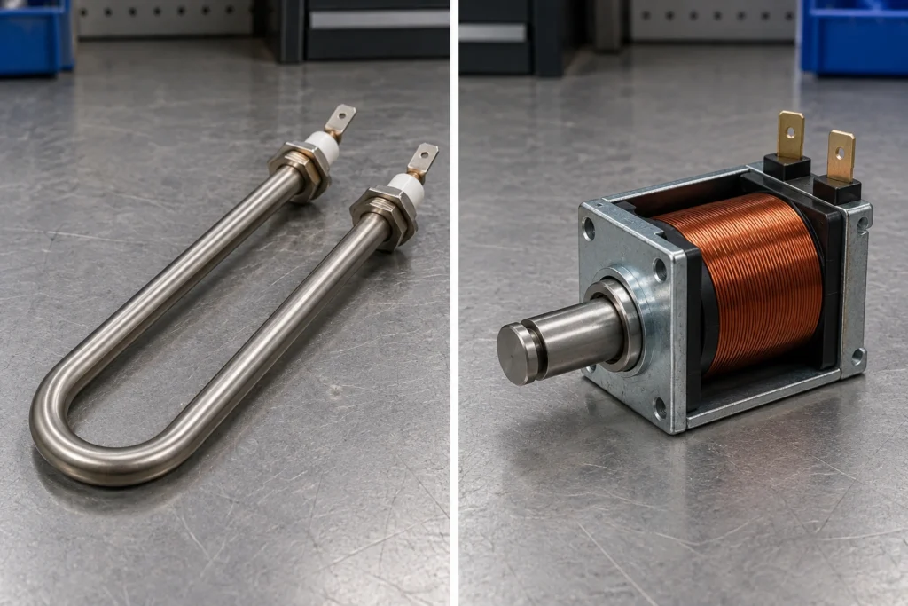
If this rate of voltage rise (dv/dt) is too steep, it can re-trigger the TRIAC into conduction without a gate signal. Preventing unintended turn-on requires a properly sized snubber and an output stage with adequate commutation ratings for the specific motor, solenoid coil, or transformer. If you are verifying a demanding inductive or high-inrush design, you can share your load and control requirements with XURUI for a compatibility and thermal review. Providing your load voltage, running and startup current, control signal, switching method, and enclosure temperature will help ensure an accurate assessment.
Frequently asked questions
How can I tell whether an SSR uses a TRIAC or SCRs?
Check the datasheet’s internal schematic or output specification for a single TRIAC versus two inverse-parallel SCRs. Housing shape, current rating, and zero-cross labels do not identify the internal silicon. If the datasheet only says “thyristor output,” verify the exact model suffix with the manufacturer.
Can a multimeter test a TRIAC-based SSR?
Not in continuity or diode mode; a multimeter’s test current is too low to latch the TRIAC. Instead, wire the SSR in series with a compatible supply and load per the datasheet. Output terminal voltage should read near full line voltage when off and drop to the specified on-state voltage when conducting. Live mains testing requires proper equipment and a qualified technician.
Can a failed TRIAC leave the load permanently on?
Yes. TRIACs typically fail short-circuit, passing full operating current to the load even after the control input turns off. Where continuous operation poses a hazard, wire an independent mechanical disconnect (such as a safety contactor) in series with the load. Never rely on the SSR input LED to confirm the output is off.
External sources
- STMicroelectronics — Thyristors and TRIACs: Latching Current
- Toshiba — Differences Among TRIAC Couplers, SSRs, and Photorelays
- Panasonic — SSR Principle of Operation
- Texas Instruments — A Modern Approach to Solid-State Relay Design
- OMRON — Solid-State Relay Terms
- OMRON — Solid-State Relay Application and Testing Information