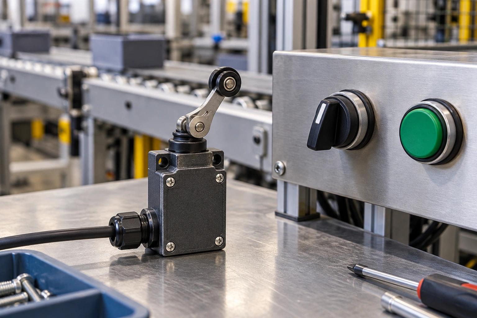
An electromechanical switch opens, closes, or redirects an electrical circuit through physical contact movement. A person, machine part, or magnetic field can trigger that movement, giving equipment a control command or position signal.
This guide compares common switch forms and explains how their contact action supports industrial tasks. It also outlines the electrical and mechanical checks needed to choose a suitable device.
What Is an Electromechanical Switch?
An electromechanical switch is a device that uses mechanically moving contacts to make, break, or change an electrical connection. Its main components are conductive contacts, wiring terminals, and an operating mechanism.
How Does an Electromechanical Switch Work?
An electromechanical switch works by converting an input action into a change in contact position.
- An operator, moving object, or magnetic field acts on the operating mechanism.
- The mechanism moves a conductive contact toward or away from another contact.
- Touching contacts complete a path for current; separated contacts interrupt it. Changeover designs transfer the connection between paths.
- When the input ends, a return mechanism may restore the original state. Maintained designs hold their selected state until another operation changes it.
In a snap-action design, stored spring energy moves the contact quickly once the actuator reaches its operating point. Slow-action contacts follow actuator movement more directly. This distinction affects response to slow-moving targets, as explained in the comparison of snap-action and slow-action switches.
Common Types of Electromechanical Switches
Common product names describe different features, so categories can overlap. A foot switch, for example, may contain a snap-action micro switch. The table groups familiar forms by their usual operating method and purpose.
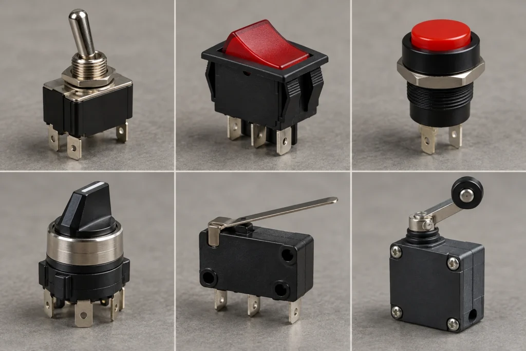
| Switch Type | Actuation Method | Typical Function | Industrial Example |
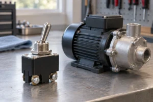
| Toggle | Lever movement | Manual command or power switching | Equipment enable control |
| Rocker | Pivoting paddle | On/off control | Instrument power control |
| Pushbutton | Button press | Start, stop, or reset command | Control panel reset |
| Rotary/selector | Knob rotation | Select a mode or circuit path | Auto/manual selection |
| Slide | Linear slider | Compact setting or switching | Instrument configuration |
| DIP | Small individual selectors | Persistent circuit settings | Device address selection |
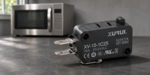
| Micro/snap-action | Plunger, lever, or roller | Detect small mechanical movement | Mechanism position confirmation |
| Limit | Machine-operated actuator | Detect a travel point | Conveyor carriage position |
| Foot | Pedal movement | Hands-free command | Assembly cycle request |
| Reed | Magnetic field | Magnetic position detection | Magnet-equipped moving part |
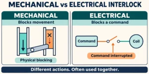
| Mechanical interlock | Guard-operated key, hinge, or actuator | Guard status detection | Machine access door |
DIP means dual in-line package, a compact arrangement often containing several small switches. Contact configuration and momentary or maintained operation describe circuit behavior rather than another physical product form.
Industrial Applications of Electromechanical Switches
In control circuits, contact changes provide operator commands or equipment-state signals that a controller interprets. Some switches also control power directly when their documented rating covers the load.
Mode Selection
A selector switch can provide separate inputs for automatic and manual operation. A programmable logic controller (PLC), the computer managing the machine sequence, reads the selected state. The selector requests a mode; the program must still enforce the conditions needed to enter that mode.
Position Detection
A moving carriage can operate a roller actuator when it reaches a defined position. The resulting signal lets the controller confirm arrival before starting another action.
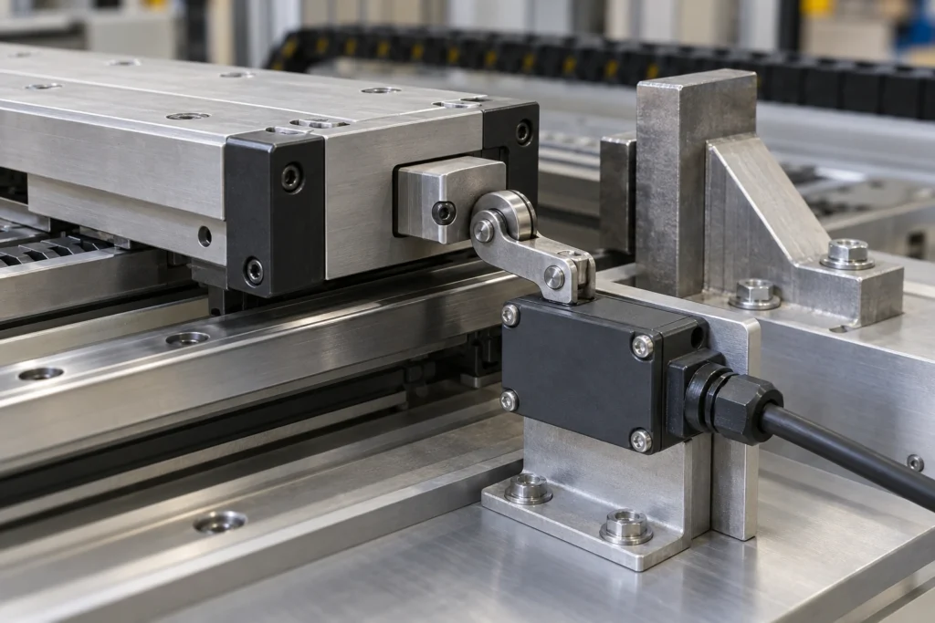
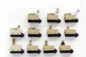
Industrial limit switches provide several actuator formats for these interfaces. The switch provides a position signal and must not carry the load that stops the moving mechanism. Where a physical end stop is required, use a separate stop designed for that load.
Cycle Control
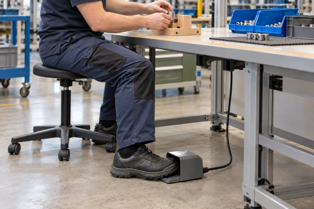
A foot switch can request a machine cycle while the operator holds a workpiece. A momentary pedal sends a temporary command, but the controller may latch that command and complete the sequence. Releasing a momentary pedal therefore does not automatically guarantee that machine motion stops.
Guard Monitoring
A mechanical guard switch detects whether a protective door is closed. For personnel protection, use a suitable safety interlock within a monitored safety system. An ordinary position switch alone does not establish a safety function.
Direct-opening switches use a direct mechanical linkage to force specified normally closed contacts open, rather than relying on a return spring. The actuator must reach the specified opening travel and force. Guard locking is needed when stopping takes longer than a person needs to reach the hazard after opening the guard.
How to Select an Electromechanical Switch
Select the required contact behavior first, then match the electrical duty and mechanical interface. These checks determine which designs can perform the task.
Contact Configuration
Use single-pole, single-throw (SPST) contacts for one on/off path. Single-pole, double-throw (SPDT) contacts select between two paths. Double-pole versions operate two separate contact paths together.
Normally open (NO) and normally closed (NC) describe the unoperated contact state. On an automatic-return changeover switch, the common terminal transfers between NC and NO. A limit switch wiring diagram illustrates these connections. Confirm terminal functions from the diagram rather than physical pin order.
Momentary or Maintained Operation
Choose momentary operation for a temporary request, such as reset or jog. The mechanism returns when the operating force is removed. Choose maintained operation when the switch must retain a selected setting, such as a mode. Neither action type determines whether its contacts are NO or NC.
Electrical Ratings and Load Compatibility
Match the rating to the actual voltage, current, and load type. An AC resistive rating does not establish suitability for a DC circuit, motor, or coil. Starting current can also exceed normal running current.
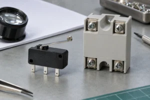
For PLC inputs, compare the input’s specified voltage and current with the contact’s minimum applicable load. Use a signal-contact version when the standard power-contact version is unsuitable for that input current. A higher maximum current rating does not guarantee reliable operation at very low current. When the load exceeds the switch’s documented duty, use a suitably rated relay or contactor to switch it. The control contacts must still handle that device’s input or coil load.
Actuator and Mounting Requirements
Choose an actuator that the target can operate in its actual direction of travel. A roller can suit a passing cam; a plunger suits a controlled push.
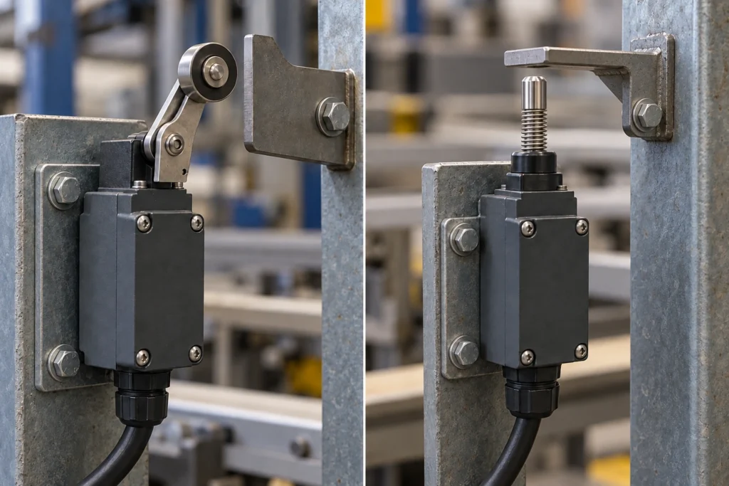
Once the actuator type is chosen, check whether the complete switch fits the installation. For a series with several actuator options, such as the XZ9 series limit switch, use the drawing for the exact version to verify mounting holes, clearance, and travel. The actuator must move far enough to operate and reset without exceeding its permitted overtravel—the allowed movement beyond the operating point.
Environmental Suitability
Choose a sealed design where dust or water could reach the contacts. The installed housing, cable entry, and seals must preserve the specified protection. Also match temperature, vibration, and chemical exposure to the model’s published limits. An ingress protection (IP) rating addresses dust and water entry; it does not by itself establish resistance to chemicals or every washdown condition.
Electrical and Mechanical Life
For loaded switching, use electrical endurance data measured under a comparable load and operating frequency. Mechanical endurance describes cycling without an electrical load and cannot predict contact life under power. Use expected daily cycles and comparable endurance data for maintenance planning. Validate the interval under actual operating conditions rather than treating the catalog cycle count as a guaranteed service life.
To narrow the options, discuss your switch requirements with XURUI. Provide circuit voltage, load type and current, contact action, actuator movement, and environment so the team can assess compatibility.
Frequently Asked Questions
What Is Contact Bounce, and How Can It Be Reduced?
Contact bounce is the brief repeated opening and closing that occurs while contacts settle. A fast input may read this as several operations. Use an input filter that rejects bounce pulses while preserving the shortest valid command.
How Can You Test an Electromechanical Switch?
Test an isolated passive-contact switch with a continuity meter while operating its actuator. First isolate all supplies, prevent restart, discharge stored electrical energy, and verify zero voltage. Disconnect external wiring paths and compare readings with the contact diagram; continuity confirms basic switching, not full load capacity.
Why Do Electromechanical Switch Contacts Stick?
Contact welding, contamination, or a failed return mechanism can leave contacts stuck. Excess current can weld the contact surfaces together, while misalignment or spring damage can prevent release. Replace damaged switches and correct the electrical or mechanical fault before restarting.
External Sources
- ARATAS — What Is an Electrical Switch?
- OMRON — Basic Switch Selection and Troubleshooting
- OMRON — Basic Switch Terminology and Durability
- OMRON — Technical Guide for Safety Components
- Texas Instruments — Debounce a Switch
- Fluke — Model 88 V Users Manual