Non-contact magnetic position sensing eliminates mechanical switch wear in automated machinery, but selecting the wrong switch parameters causes erratic triggering, contact chatter, and premature circuit failure. When specifying a normally open reed switch, engineers often overlook magnetic field orientation, contact inrush from cable capacitance, and pull-in hysteresis margins.
This guide outlines practical selection checks for Form A normally open reed switches in position sensing. It examines contact mechanics, sensitivity bands, motion profiles, electrical protection, mechanical mounting checks, and industrial specification criteria.
How Form A Normally Open Reed Contacts Actuate Under Magnetic Flux
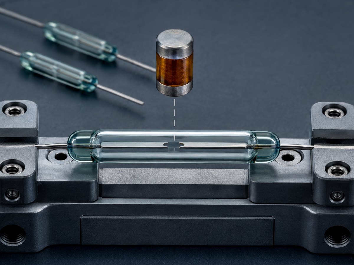
A Form A normally open reed switch uses magnetic flux to pull two flexible ferromagnetic blades together, completing an electrical circuit without mechanical actuators or external power. Partnering with a proven reed switch supplier ensures internal contact plating and fill gases match industrial duty cycles.
Ferromagnetic Blade Polarization and Contact Closure
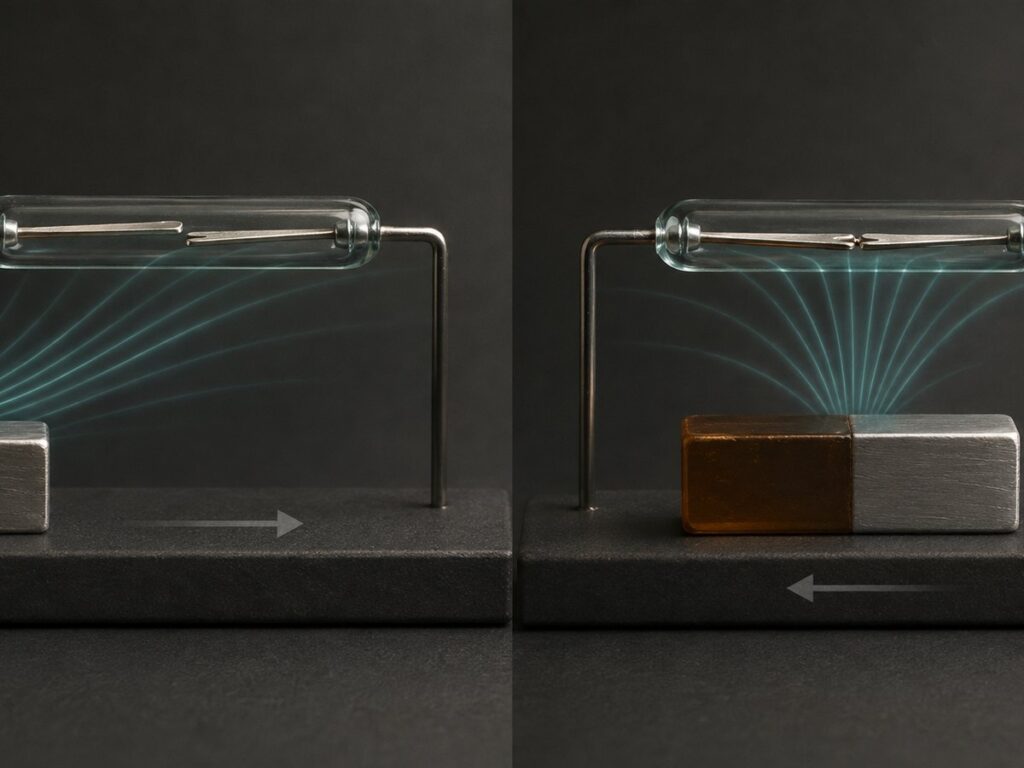
The core mechanism consists of two cantilevered reeds made from nickel-iron alloy, plated with rhodium or ruthenium, and separated by an open gap. When a permanent magnet enters the sensing zone, magnetic flux travels through both reeds. This field induces opposite magnetic polarities at the overlapping contact tips, creating north and south poles that attract. Once magnetic attraction exceeds blade spring stiffness, the contacts close in under 1.5 milliseconds. When the magnet withdraws, field strength drops below the mechanical restoring force, and the elastic reeds return to their open resting state.
Hermetic Glass Sealing and Contact Atmosphere Protection
The contact blades remain hermetically enclosed inside a borosilicate glass capsule filled with dry inert gas, such as nitrogen or argon, or evacuated under vacuum. This envelope prevents ambient air, moisture, dust, cutting fluids, and corrosive fumes from reaching the contact interface. Because no oxygen enters the capsule, contacts resist oxidation over millions of switching cycles. This sealing allows normally open reed switches to switch millivolt dry circuits reliably, whereas open mechanical contacts frequently suffer from film accumulation and signal dropouts.
Evaluating Ampere-Turn Sensitivity Bands and Hysteresis Margins
Ampere-turns (AT) measure reed switch magnetic sensitivity, defining the coil force needed to close the open contacts.
| Parameter | Typical Value Band | Sensing Implication | Design Action |
|---|---|---|---|
| Pull-In Sensitivity | 10 to 30 AT (High Sensitivity) | Detects weak fields or operates at extended air gaps | Use for compact magnets and battery-powered sensors |
| Pull-In Sensitivity | 60 to 100 AT (Low Sensitivity) | Requires strong magnetic flux to trigger | Use in high-vibration zones and noisy magnetic areas |
| Drop-Out Ratio | 40% to 70% of Pull-In AT | Contacts stay closed past the initial pull-in distance | Factor differential travel into machine reset logic |
| Contact Resistance | 100 to 200 mΩ maximum | Minimal voltage drop across dry circuit signals | Verify total loop impedance for low-voltage PLC inputs |
Matching Pull-In Sensitivity to Actuator Magnet Strength
Selecting an AT band balances operating distance against stray field immunity. Understanding what AT means helps engineers interpret coil pull-in ratings and match magnet grades to mechanical gaps. Switches rated 10 to 30 AT actuate in weak magnetic fields, fitting miniature magnets or wide air gaps. However, high sensitivity increases vulnerability to false trips from nearby relays, motors, or machine vibration. Switches rated 60 to 100 AT require higher flux to close, providing strong noise immunity. For automated machinery, engineers select higher AT bands paired with strong permanent magnets to maintain repeatable switching thresholds.
Calculating Drop-Out Distance and Positioning Hysteresis
Normally open reed switches exhibit magnetic hysteresis, meaning drop-out occurs at a weaker field than pull-in. Once reeds touch, the air gap disappears, lowering magnetic reluctance and holding contacts closed as the magnet retreats. In position sensing, drop-out distance is 20% to 40% greater than initial pull-in distance. Machine designers must account for this differential travel when programming position limits on actuators or cylinders, ensuring the target clears the drop-out boundary before triggering the next state.
Selecting Magnetic Actuation Profiles to Prevent False Double Pulsing
The approach angle and travel axis of the actuator magnet determine the magnetic field profile across the glass capsule, directly affecting switching consistency.
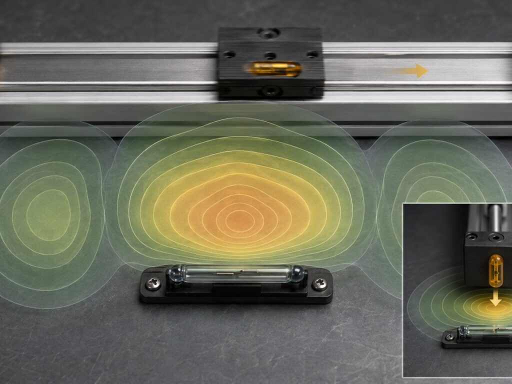
Head-On Approach for Direct Proximity Detection
In a head-on motion profile, the actuator magnet moves perpendicular to the reed switch, traveling directly toward the center overlap of the contacts. This setup provides high positional repeatability along the approach axis, making it effective for door interlocks, end-of-stroke stops, and safety guard closure detection. Designers must align the magnetic pole axis parallel with the longitudinal axis of the switch. If a magnet approaches with its poles aligned across the narrow width of the capsule, flux lines split evenly between both reeds, reducing attraction and creating inconsistent actuation gaps.
Slide-By Motion and Multi-Lobe Magnetic Fields
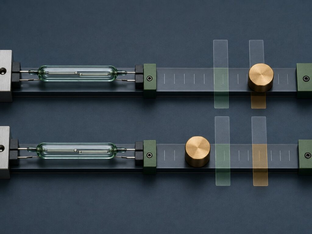
Slide-by actuation occurs when a magnet travels parallel to the long axis of the switch, which is standard in pneumatic cylinder sensors and liquid level float switches. A permanent magnet creates three distinct sensitivity lobes across a reed switch: a dominant central lobe and two smaller secondary lobes near the capsule ends. If the magnet passes too close to a high-sensitivity switch, contacts can close at the first end lobe, open in the intermediate valley, close again at the center, and repeat at the far end. To eliminate this false double pulsing, designers increase lateral clearance or select a lower sensitivity AT band that responds only to the center lobe.
Rotary Actuation for Pulse Counting and Flow Metering
Rotary actuation mounts actuator magnets on a spinning shaft, disk, or impeller that sweeps past a stationary normally open reed switch. Each revolution sweeps magnetic flux past the capsule, generating discrete pulses up to 500 Hz. When comparing reed switches versus Hall effect sensors, zero standby current makes passive reed elements ideal for battery-powered telemetry where active sensors drain power. This configuration is widely deployed in water meters, gas counters, anemometers, and conveyor tachometers.
Electrical Load Protection in Position Sensing Circuits
Because reed switches use low-mass contact blades with microscopic contact points, unsuppressed electrical transients cause contact welding or pitting within early operating cycles.
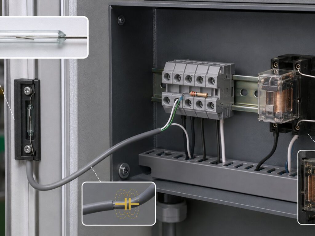
Suppressing Cable Capacitance and Inrush Currents
Cable runs between a reed sensor and control cabinet introduce distributed capacitance, typically 50 to 100 picofarads per meter. When normally open contacts close in a 24VDC circuit, stored charge discharges instantly through the closing contact tips. Uncontrolled capacitive discharge is a primary reed switch failure cause, melting plating and welding blades together. Installing a small resistor of 22 to 100 ohms in series with the switch, positioned directly adjacent to the glass body, damps capacitive discharge and preserves contact life.
Clamping Inductive Flyback From Coils and Relays
When a normally open reed switch directly drives an inductive load, such as an auxiliary relay coil, magnetic counter, or solenoid valve, breaking the circuit induces high-voltage inductive flyback. As contacts separate, the collapsing magnetic field in the coil generates negative voltage spikes reaching hundreds of volts, striking an electrical arc across the microscopic contact gap. For DC circuits, placing a fast recovery freewheeling diode across the coil clamps inductive spikes safely. For AC circuits, connecting a series resistor-capacitor snubber across the reed contacts suppresses arc discharge and prevents contact erosion.
Mechanical Handling and Enclosure Protection Checks
The borosilicate glass envelope provides environmental isolation, but improper mechanical mounting or lead preparation will destroy the hermetic seal.
Trimming and Bending Leads Without Glass Seal Fracture
Terminal leads consist of iron-nickel wire bonded to the glass envelope through a matched thermal expansion seal. Bending or trimming a lead puts mechanical shear stress directly onto this glass-to-metal boundary, risking micro-cracks that allow gas leakage and moisture ingress. When forming leads for terminal blocks or printed circuit boards, technicians must clamp the lead firmly with flat-nose pliers between the glass body and bend location. This clamping absorbs bending torque, preventing mechanical force from reaching the glass seal.
Preventing Magnetic Shunting From Ferrous Brackets
Mounting reed switches or actuator magnets on structural steel plates, cast iron frames, or brackets containing ferrous metals alters the magnetic path. Ferrous metals exhibit high magnetic permeability, acting as magnetic shunts that divert flux lines away from internal reed blades. This shunting effect can reduce effective sensing distance by more than 50% or prevent pull-in entirely. When designing mounting fixtures, engineers specify non-magnetic materials, such as aluminum, brass, 316 stainless steel, or engineered plastics, to preserve natural magnetic field geometry.
Specifying Xurui XGH Reed Switches for OEM Sensing Assemblies
Zhejiang XURUI Electronics manufactures the XGH series reed switch line, giving automation builders and sensor OEMs reliable Form A contacts across standard glass dimensions.
| Model Size | Capsule Dimensions | Maximum Switching Voltage | Maximum Carry Current | Sensitivity Options | Primary Sensing Role |
|---|---|---|---|---|---|
| Miniature XGH | φ2.0 mm × 10.0 mm | 100 VDC | 0.5 A | 10 to 25 AT | Compact pneumatic cylinders and portable sensors |
| Standard XGH | φ3.0 mm × 20.0 mm | 220 VDC | 1.0 A | 15 to 40 AT | Machine position limits and security interlocks |
| Heavy-Duty XGH | φ5.0 mm × 30.0 mm | 220 VDC | 2.5 A | 30 to 70 AT | Industrial float switches and material handling lines |
| High-Power XGH | φ8.0 mm × 50.0 mm | 220 VDC | 4.0 A | 60 to 100 AT | Heavy machinery and high-vibration equipment |
Selecting Capsule Dimensions for Confined Enclosures
The XGH series reed switch family covers tube diameters from φ2 mm to φ8 mm and lengths from 10 mm to 50 mm. Miniature sizes, such as φ2×10 mm, fit narrow pneumatic tracks, medical fixtures, and float stems where space is constrained. Larger capsules, such as φ5×30 mm and φ8×50 mm, provide wider reeds and higher contact mass, supporting carry currents up to 4A while resisting shock and vibration in heavy machinery.
Requesting Custom AT Bands and Prototype Samples
Because sensing distance depends on mechanical tolerances and magnet grades, Xurui offers factory-calibrated AT bands. Sourcing teams can order tight groups, such as 10 to 30 AT for proximity detection or 60 to 100 AT for strong-field controls. Testing engineering samples in realistic assemblies confirms pull-in and drop-out distances, helping engineers qualify components from Xurui before approving high-volume production orders.
Frequently Asked Questions
Can a Normally Open Reed Switch Be Configured for Normally Closed Operation Without Replacing the Switch?
Yes, a normally open Form A reed switch functions as a normally closed sensor when paired with a stationary biasing permanent magnet. Mounting the biasing magnet adjacent to the glass capsule provides continuous magnetic flux, holding contacts closed in the resting state. When an external actuator magnet with opposite polarity approaches, its field cancels the biasing flux, allowing mechanical spring tension to snap contacts open. This technique creates a normally closed safety or door monitor circuit using standard normally open components.
How Does Operating Temperature Affect Magnetic Sensing Distance and Pull-In Consistency?
Operating temperature alters magnetic sensing distance primarily by degrading the flux density of the actuator magnet rather than changing the mechanical properties of the reed blades. Neodymium iron boron magnets experience a reversible flux loss of approximately 0.11% per degree Celsius rise, whereas ceramic ferrite magnets lose roughly 0.20% per degree Celsius. In high-temperature machinery, this reduced flux weakens the field at the switch, shrinking the effective pull-in distance unless designers compensate with a lower AT sensitivity switch or closer initial mounting clearance.
Why Does a Reed Switch Produce Contact Bounce, and How Should PLC Inputs Filter It?
A reed switch produces contact bounce because its flexible metal reeds collide and physically rebound repeatedly before settling into continuous electrical conduction. This mechanical oscillation typically lasts between 0.1 and 0.5 milliseconds, which high-speed digital inputs or microcontroller interrupt counters can record as multiple rapid switching pulses. Control engineers eliminate false triggers by programming a 2 to 5 millisecond software debounce filter in PLC ladder logic or installing a simple hardware resistor-capacitor filter across the digital input terminal.
XURUI Engineering Team

Industrial SPST toggle switch on a control panel](https://xuruiswitch.com/wp-content/uploads/2026/09/spst-toggle-switch-industrial-control-cover-300x225.webp)
SPST toggle switch product on a clean electronics workbench](https://xuruiswitch.com/wp-content/uploads/2026/09/spst-toggle-switch-cover-300x225.webp)