
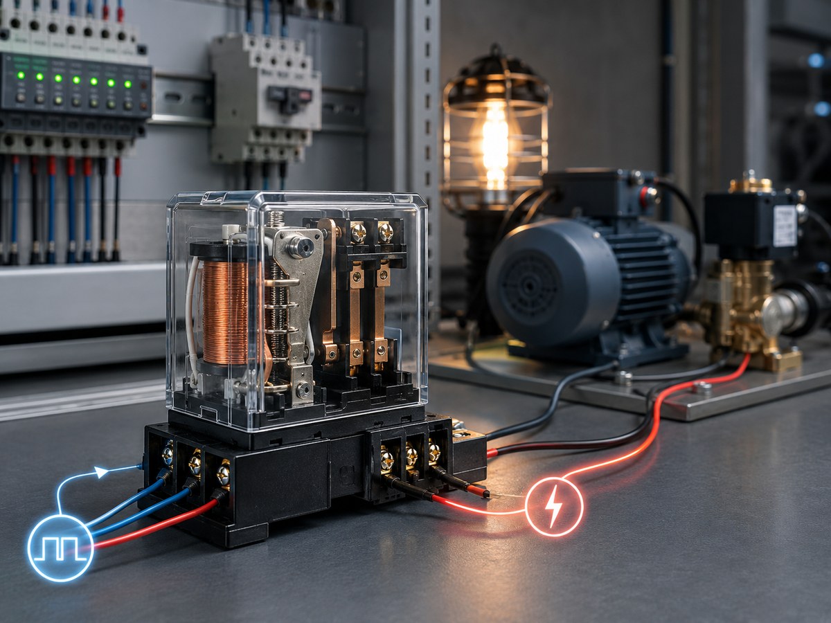
A relay is an electrically controlled switch that uses a small signal to turn another circuit on or off. In control panels, a PLC, sensor, timer, or manual switch can use a relay to control a contactor coil, alarm, valve, heater, fan, pump, or other load without carrying full load current.
Engineers use relays when the control signal is too small, the load uses a different voltage, or the circuit needs isolation between the controller and the power side. This guide covers relay working principles, relay types, common uses, and selection checks without mixing up mechanical relay and solid state relay behavior.
How Does a Relay Work?
A relay works by letting an input signal change the state of an output circuit. Mechanical relays do this with a coil and moving contacts. Solid state relays do this with semiconductor output devices.
Electromechanical Switching Sequence
An electromechanical relay has a coil, magnetic core, armature, spring, and contact set. When the coil receives the correct voltage, the magnetic field pulls the armature and changes the contact state. When coil voltage drops out, the spring returns the armature and contacts to their normal position.
This sequence only describes a mechanical relay. An SSR has no armature or mechanical contacts.
Normally Open and Normally Closed Contacts
Normally open and normally closed describe the contact state when the relay is not energized. A normally open contact closes when the relay operates. A normally closed contact opens when the relay operates.
Contact form affects what the circuit does during power loss, controller failure, or emergency stop logic. For a deeper contact-state explanation, see normally open vs normally closed switch.
Solid State Switching Without Moving Contacts
A solid state relay switches through semiconductor devices instead of mechanical contacts. The input side triggers an internal circuit, often with optical or transformer isolation, and the output side switches the load electronically.
An SSR does not click, bounce, or wear contacts like a mechanical relay. The tradeoff is different: an SSR produces heat during conduction, can have small off-state leakage current, and must match the AC or DC load type. For more detail, see how a solid state relay works.
What Are the Main Types of Relays?
Common relay types include electromechanical, reed, time delay, safety, and solid state relays. The right type depends on the load, signal, timing, safety function, and switching frequency.
Electromechanical Relays
Electromechanical relays use a coil to move contacts. They suit standard control loads, interposing duty, and circuits that need visible contact behavior, but the contacts can arc, bounce, pit, or wear.
Reed Relays
Reed relays use a magnetic field to operate sealed reed contacts, usually inside a glass tube. They suit low power signal switching, sensing, compact control circuits, and test equipment, but the contact rating must match the tube size and datasheet.
Time Delay Relays
Time delay relays add timing to the switching action. They may delay on, delay off, pulse for a set time, or sequence circuits in motor starting, fan purge, pump staging, and alarm delay circuits.
Safety Relays
Safety relays monitor inputs such as emergency stop buttons, guard switches, light curtains, or interlock devices. They belong in safety-related control circuits and should follow the machine risk assessment, device manual, and applicable safety standards.
Do not replace a safety relay with a general control relay. The two parts may both switch outputs, but they do not provide the same safety function.
Solid State Relays
Solid state relays use semiconductor switching. SSRs fit high cycle control, quiet switching, heater control, lighting control, and automation loads with frequent operation.
| Relay type | How it works | Common use | Key caution |
|---|---|---|---|
| Electromechanical relay | Coil moves mechanical contacts | General control, contactor coils, alarms | Contacts can wear or arc |
| Reed relay | Magnetic field operates sealed reeds | Low power signals, sensing, test circuits | Limited load current |
| Time delay relay | Output changes after a timed function | Start delays, off delays, sequencing | Timing mode must match logic |
| Safety relay | Monitors safety inputs and outputs | Emergency stop, guard door, interlock circuits | Must match safety design |
| Solid state relay | Semiconductor output switches the load | Heater, lighting, high cycle automation | Needs heat and AC/DC checks |
Where Are Relays Used in Electrical Control?
Engineers use relays to switch, isolate, delay, interlock, or repeat electrical actions. In industrial control, relays sit between sensors, PLC outputs, operator devices, timers, safety devices, and load circuits.
Industrial Automation Panels
Automation panels use relays to connect low power PLC outputs to field devices, indicator lamps, solenoid valves, alarms, and contactor coils. A relay can also provide a dry contact, which is a contact output that does not supply its own voltage.
Motor, Pump, And Fan Circuits
Motor, pump, and fan circuits often use relays for control logic rather than direct motor power. A relay may start a contactor coil, enable a drive input, switch an alarm, or prove a condition before a machine runs.
Heating and Temperature Control
Heating circuits use relays to turn heaters on and off from a thermostat, temperature controller, PLC, or process controller. Mechanical relays can work in lower cycle systems. SSRs are common when the controller switches often to hold temperature closely.
Machine Safety and Interlock Circuits
Machine safety circuits use relays and interlock devices so a guard, door, access cover, or emergency stop condition affects machine operation. The interlock device reports the condition, while the safety relay or safety controller handles monitored outputs.
How Is a Solid State Relay Different from a Mechanical Relay?
A solid state relay uses a semiconductor output instead of moving contacts. A mechanical relay gives physical contact opening. An SSR switches quietly and handles frequent operation well, but it needs heat and leakage current checks. For a closer comparison, see solid state vs electromechanical relays.
Moving Contacts and Semiconductor Outputs
A mechanical relay changes a physical contact gap. A solid state relay uses an electronic output path, so no armature or contact gap moves.
Switching Frequency, Noise, And Contact Wear
Mechanical relays click because parts move. They fit slower cycles and simple isolation tasks. SSRs fit frequent switching because no contacts wear.
Heat Dissipation and Leakage Current
Mechanical relay contacts usually produce little heat when closed and healthy. An SSR drops voltage across its output device while current flows, which creates heat. An SSR can also pass a small leakage current when off.
Load Matching and Application Fit
Mechanical relays must match contact voltage, contact current, load behavior, coil voltage, and contact form. SSRs must match input signal, output AC or DC type, load current, surge current, and heat path.
| Factor | Mechanical relay | Solid state relay |
|---|---|---|
| Switching element | Moving contacts | Semiconductor output |
| Sound | Audible click | Quiet switching |
| Contact wear | Contacts can wear | No mechanical contact wear |
| Off-state leakage | Usually open contact behavior | Small leakage can exist |
| Heat | Low at healthy contacts | Thermal path often needed |
| Typical fit | General control and isolation | High cycle or quiet switching |
How Do You Choose the Right Relay for a Circuit?
Choose a relay by checking the load side, control side, switching stress, installation, and required approvals. A relay that looks correct by current rating alone can still fail if the voltage type, coil, heat path, or load behavior is wrong.
Use this order before comparing models:
- Confirm load: voltage, current, AC or DC, inrush, and duty cycle.
- Confirm control: coil or input voltage, output current, and contact form.
- Check stress: inductive load, surge, switching rate, leakage current, and heat.
- Check installation: mounting, airflow, terminals, environment, and certifications.
Load Voltage, Current, And AC/DC Type
Start with the load, not the relay package. Check AC or DC type, normal current, inrush, voltage, duty cycle, and whether the relay must make, break, or only carry the current. An undersized relay may overheat, weld, or lose contact quality. A higher current number does not fix an AC/DC mismatch.
Control Voltage and Contact Form
The relay input must match the control source. A mechanical relay coil may be 12VDC, 24VDC, 110VAC, 230VAC, or another rating. An SSR input also has voltage and current limits. The wrong coil or input voltage can cause no operation, overheating, buzzing, or early failure.
Then check contact form. NO and NC describe the rest state. SPST, SPDT, and DPDT describe the number of poles and throws, which decides circuit count and whether the relay can change between two output paths.
Load Behavior, Switching Frequency, And Heat
Resistive, inductive, capacitive, and electronic loads stress relays differently. Motors, solenoids, transformers, and long cable runs can create surge current or voltage spikes. These loads may need derating, suppression, or a different relay type.
Switching frequency also changes the choice. A mechanical relay may be fine for occasional operation, but frequent cycling can wear contacts. An SSR may fit frequent switching, but the heat sink must match the load current and cabinet conditions. For SSR thermal selection, see Do solid state relays need a heatsink.
Mounting, Environment, And Certifications
Mounting affects wiring, service, and heat. Plug-in relays, PCB relays, DIN rail relays, panel mount SSRs, and safety relays fit different layouts. Check cabinet temperature, airflow, dust, oil, vibration, terminal access, and certifications by series or model.
Xurui Switch has manufactured industrial control switches since 2002 and supplies quote-based B2B products for automation and control panels. Its solid state relay supplier range includes single-phase, three-phase, DIN rail, compact, monitoring, and current-protection SSR options.
FAQs
Can a relay click and still be bad?
Yes, a relay can click and still be bad. The click usually means the coil or actuator moved, but burned contacts, weak contact pressure, internal cracks, or high resistance can still keep the load from working.
Why does a relay buzz or chatter?
A relay may buzz or chatter when the coil voltage is low, unstable, or mismatched to the relay rating. Loose wiring, a weak power supply, controller output pulsing, vibration, or contact bounce can also cause it.
Can a relay be replaced with a higher current rating?
You can use a higher current relay only when the coil or input voltage, contact form, load type, terminal layout, mounting, timing, and safety role also match. A higher amp rating does not solve a wrong coil voltage or AC/DC mismatch.
Can a DC relay be used for AC, or an AC relay for DC?
Do not swap AC and DC relays unless the datasheet approves that exact use. AC and DC coils behave differently, contacts interrupt AC and DC arcs differently, and SSR outputs are load-type specific.
Why add a diode, MOV, or RC snubber to a relay circuit?
A diode, MOV, or RC snubber limits voltage spikes from a relay coil or inductive load. That protection can reduce arcing, electrical noise, and stress on PLC outputs, sensors, contacts, or semiconductor outputs.
Conclusion
A relay is simple in purpose but sensitive to load and control details. Choose by load voltage, current, AC or DC type, control voltage, contact form, relay type, heat, mounting, environment, and required approvals.
XURUI Engineering Team






