In industrial automation, the phrase “12V solid state relay” creates immediate confusion on a bill of materials. It can describe a relay driven by a 12V control signal, a unit switching a 12V DC load, or a multi-channel board powered by a 12V auxiliary rail. An SSR functions purely as an isolated semiconductor switch rather than a power supply, so it never outputs a regulated 12V rail on its own. Avoiding bench errors requires evaluating the input trigger and load switching stages as two electrically separate circuits.
How to Identify What 12V Means on the Label
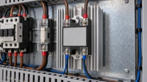
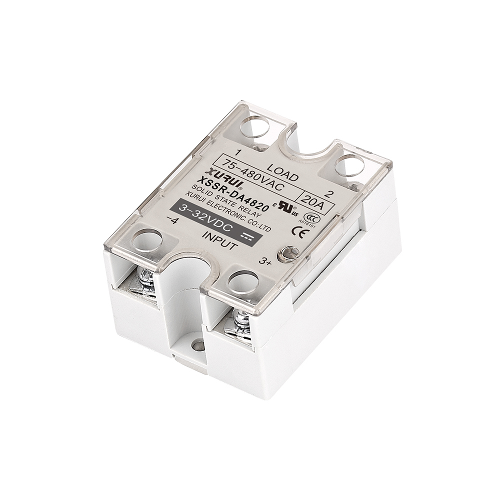
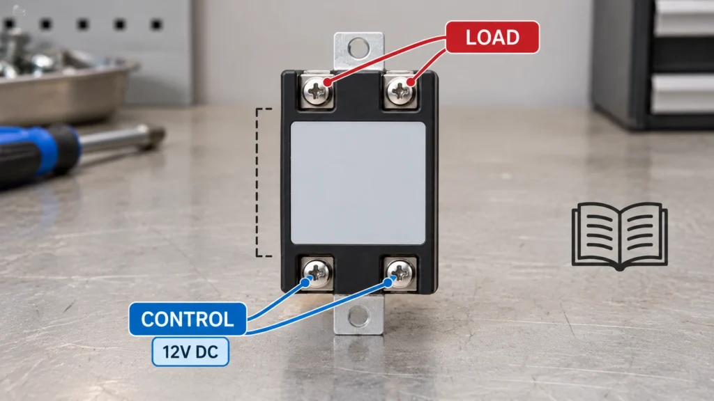
Clear terminal labeling remains your first defense against miswiring before consulting full documentation. Industrial SSR housings physically divide control and load circuits. Look for “Input” or “Control” on the low-power side, and “Output” or “Load” across the switching path. Terminal screw positions and pin layouts vary across hockey-puck, PCB-mount, and DIN-rail packages, so never wire based on physical orientation alone. If housing markings are abbreviated or obscured by dust, verify the complete part number against the manufacturer datasheet before applying power.
Input Voltage Range
The input rating specifies the drive signal needed to bias the internal optocoupler LED. A 12V control source can satisfy either a narrow nominal window (such as 9 to 15V DC) or a wide-input receiver (typically 3 to 32V DC). This trigger voltage has no relation to the voltage rating of the output contacts.
On multi-channel relay boards with separate power terminals, separate the main supply rail (VCC) from the logic trigger pins (IN). A board that requires a 12V auxiliary supply often restricts logic pins to 3.3V or 5V signals. Interfacing a 12V PLC output directly to these low-voltage logic pins will destroy the onboard optocouplers.
Trigger Requirements
Reliable switching requires satisfying both voltage and loop current requirements under actual load. The control source must supply the minimum turn-on current (commonly 5 to 20 mA) while holding the specified must-operate voltage. Measuring an open-circuit voltage with a high-impedance meter will hide controller drive limitations. Turn-off thresholds matter just as much: the control line must drop below the release voltage to prevent false latching from residual leakage.
Standard industrial hockey-puck SSRs incorporate internal constant-current regulation, but bare PCB-mount solid-state relays often demand external current-limiting resistors. Grounding your design in basic solid state relay input and output operation prevents premature optical degradation and erratic field switching.
Load Voltage Range
The load rating defines the permissible operating window for the external power supply and equipment. High-voltage ratings do not ensure low-voltage compatibility. If circuit voltage drops below the minimum conducting threshold of the output stage, the semiconductor switch will fail to turn on cleanly.
On nominal 12V DC circuits, assess the entire operating envelope of your power rail. Lead-acid and lithium battery systems regularly swing between 10.5V and 14.8V, with inductive switching transients extending beyond those limits. Continuous operating ratings must cover these worst-case rail variations without relying on surge withstand limits for daily operation.
Output Type
Output silicon determines which supply waveforms the relay can interrupt. AC models rely on thyristors (TRIACs or back-to-back SCRs) that extinguish only when load current crosses zero. DC outputs require power MOSFETs or bipolar power transistors to interrupt continuous direct current. While specific back-to-back MOSFET topologies switch both AC and DC, bidirectional operation requires explicit datasheet confirmation.
Markings such as “DC Input” refer exclusively to the control side. An AC output triggered by a 12V DC signal remains an AC-only switch. Following established AC and DC solid state relay wiring prevents output latch-up, miswired polarity, and immediate device destruction during commissioning.
A 12V Control Input Can Switch a Different Load Voltage
Complete optical isolation across the internal barrier frees the control logic from any dependency on the load operating voltage. A 12V DC control signal simply illuminates an internal infrared emitter, enabling the output semiconductor to govern an entirely different power circuit.
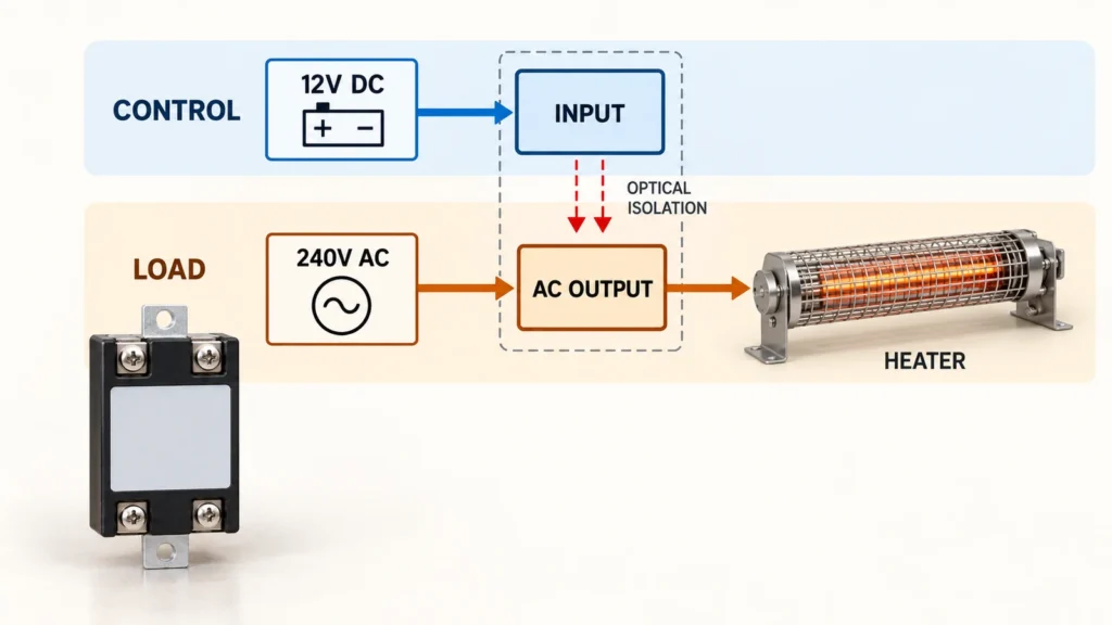
The industry-standard Omron G3NA-210B-UTU DC5-24 exemplifies this configuration. Its input terminal accepts 5 to 24V DC, accommodating standard 12V PLC logic without external dropping resistors. Its output, however, switches 24 to 240V AC mains. Field technicians frequently use 12V DC control signals to switch 120V or 240V AC heaters, valves, and fractional-horsepower motors.
Voltage compatibility is only the baseline check. Engineers must still account for inrush currents, power factor, thermal derating, and cycling frequency before finalizing selection.
Switching a 12V DC Load Requires a Compatible Output
Switching an actual 12V DC load introduces strict semiconductor constraints that never apply to alternating-current systems.
DC Output Requirements
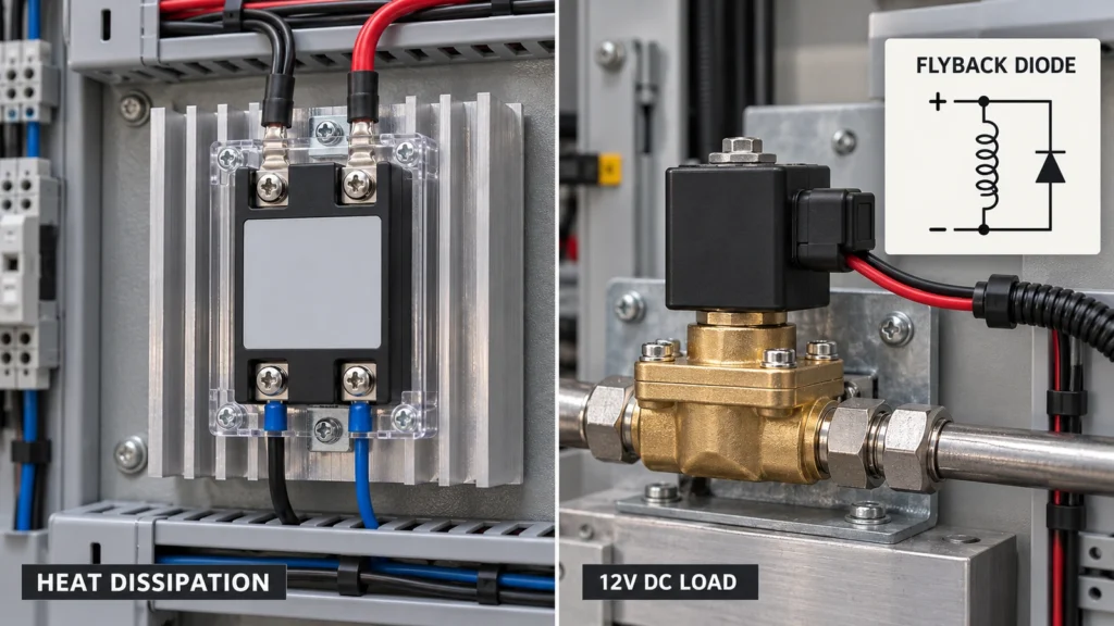
DC circuits lack natural zero-crossing points, placing entire inductive and inrush stresses on the output semiconductor. When switching 12V DC, specify continuous current ratings that absorb inrush peaks from DC motors, capacitive driver circuits, and solenoids. Selecting validated solid state relays for DC loads ensures the internal output stage integrates correct clamp diodes and handles inductive flyback energy safely.
Thermal dissipation demands rigorous scrutiny in low-voltage circuits. Delivering substantial wattage at 12V requires high current, causing heavy conduction losses across the internal on-state resistance (RDS(on)) or forward diode drop. A 12V load pulling 30A will overheat an uncooled hockey-puck SSR within minutes. Sizing heatsink thermal resistance against peak enclosure ambient temperatures keeps junction temperatures safely below manufacturer maximums.
AC Output Limitations
Wiring a 12V DC load to an AC-output relay creates an immediate latch-up fault. Thyristors and TRIACs require current to fall below their holding threshold to release. Without periodic zero-crossings in steady DC, an AC relay triggered by a 12V signal latches permanently into conduction, ignoring the removal of the control input. Disconnecting the DC power rail is the only way to reset it.
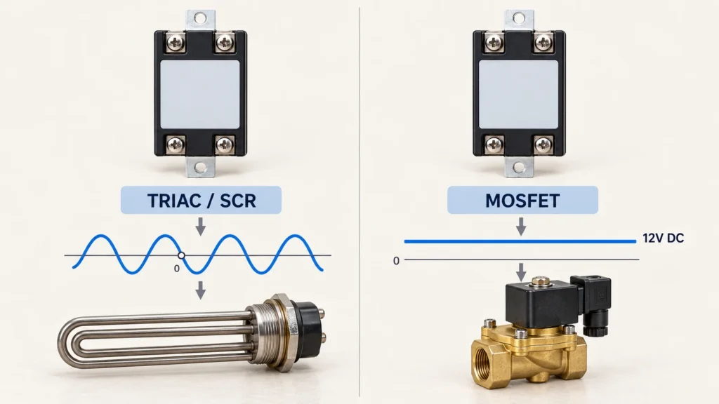
Label terms like “zero-crossing” and “random turn-on” apply strictly to AC waveforms and will not solve DC latching problems. In addition, semiconductors exhibit continuous microampere leakage in the off state and typically fail as short circuits. For maintenance safety, install a physical mechanical disconnect upstream rather than relying on a de-energized SSR for lockout-tagout protection.
Describing Your 12V SSR Requirements
Clear purchase specifications prevent field delays by defining both sides of the optical barrier up front.
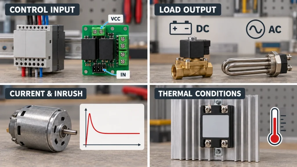
Ambiguous requests like “I need a 12V SSR” force distributors to guess your load parameters. Replace informal terms with explicit electrical statements:
- Example 1 (12V Control Side): Accept a 12V DC control signal (or a 3 to 32V DC wide-input range) to switch a 240V AC resistive heater at 15A continuous load current.
- Example 2 (12V Load Side): Switch a 12V DC inductive solenoid drawing 8A continuous and 35A peak inrush, controlled by a 5V microcontroller logic output.
Always document inrush profiles, cycling rates, suppression flyback diodes, and enclosure temperatures. When upgrading legacy panels, you can request an SSR application review from XURUI by submitting schematic captures and field measurements to verify thermal and electrical margins before ordering hardware.
Frequently Asked Questions
Can a 12V Solid State Relay Be Used for PWM Control?
Only if the unit utilizes a high-speed DC MOSFET output stage. Standard AC zero-crossing SSRs cannot track PWM signals due to turn-off delays locked to 50/60 Hz half-cycle boundaries (8.3 ms or 10 ms). For DC pulse-width modulation, choose fast-switching DC models: Sensata’s HDC Series, for example, supports PWM frequencies up to 1 kHz when factoring in turn-on and turn-off switching times along with thermal frequency derating.
Why Does an LED Stay Dimly Lit When the SSR Is Off?
Off-state leakage current passing through the semiconductor junction or internal RC snubber causes this symptom. While high-current motors ignore minor leakage, high-efficiency LED indicators illuminate on microamperes. A faint glow does not indicate a blown relay. Installing a properly sized bleeder resistor in parallel across the load or selecting a low-leakage SSR shunts this residual current and extinguishes the light.
Can You Test a 12V Solid State Relay With a Multimeter?
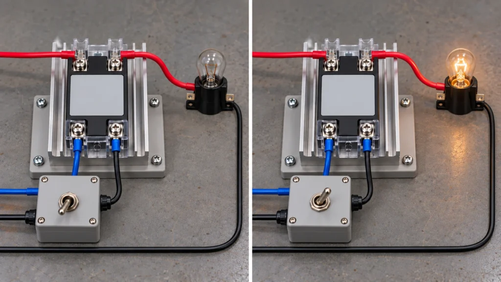
Standard multimeter continuity and resistance modes cannot verify SSR health. The meter’s internal 9V or coin-cell battery cannot supply the bias voltage and minimum holding current required to drive output semiconductors into conduction. Bench testing requires wiring the relay to a live DC power source and an actual load. Following systematic solid state relay troubleshooting tips confirms both full conduction and complete release without misdiagnosing functional components.
References & Authoritative Sources
- Omron Technical Explanation for Solid State Relays
- Omron G3NA Solid State Relay Specifications
- Sensata HDC Series Panel Mount Solid State Relay Datasheet