Industrial relay terminal numbers identify a coil or contact function. They do not always show where a connection sits on the socket. That distinction matters when replacing or wiring a plug-in relay in an industrial control panel.
This guide covers common electromechanical relay markings, one documented socket map, and terminal conventions for overload relays, contactors, and safety relays.
The Universal Logic Behind Relay Terminal Numbers
On many control relays, lettered terminals identify the coil and numbered groups identify the contacts. These markings describe circuit function; the relay and socket diagrams show the physical locations.
The Two-Digit Code Explained
For a changeover contact, 11 is common, 12 is normally closed (NC), and 14 is normally open (NO). The reference state is when the coil is de-energized: 11 connects to 12. Energizing the coil transfers the connection to 14. A second changeover contact commonly uses 21, 22, and 24; a third uses 31, 32, and 34.
A two-digit marking does not always indicate a changeover contact. A simple NO contact may use 13–14; it has no common terminal that switches between NC and NO. The contact diagram identifies the arrangement.

Standard Coil Terminal Markings
A1 and A2 identify the coil terminals, separate from the switched contacts. Match the coil’s specified AC or DC voltage before applying power. On a polarized DC coil, connect A1 to positive and A2 to negative when those markings appear on the relay or its indicator or suppression module. An unmarked, nonpolarized DC coil has no required polarity.
Why Your Relay Socket Shows Two Different Sets of Numbers
A socket may show contact-function labels alongside physical pin numbers. Contact labels identify what each contact does; pin numbers locate the connections on that particular base. Use the exact relay and socket diagrams to translate between them.
The ComatReleco EC-11 socket provides one documented mapping:
| Contact-function terminal | EC-11 physical pin | Function |
| A1 / A2 | 2 / 10 | Coil |
| 11 / 12 / 14 | 1 / 4 / 3 | First common / NC / NO |
| 21 / 22 / 24 | 6 / 5 / 7 | Second common / NC / NO |
| 31 / 32 / 34 | 11 / 8 / 9 | Third common / NC / NO |
On the EC-11, functional terminal 11 is physical pin 1, while physical pin 11 carries terminal 31. Another socket may map them differently. Match the relay and socket models, then follow the viewing direction shown in their diagrams. A relay’s bottom view reverses left and right compared with viewing its socket from above. When tracing these connections across a panel, a panel wiring diagram can help distinguish terminal labels from wire numbers and device tags.
Common Relay Pinout Configurations and Terminal Numbers
Pin count tells you how many connections reach the base, but not where each function sits. The configurations below describe common changeover relays; use the matched relay and socket diagrams for physical pin assignments.
8-Pin Relay Wiring
An 8-pin, two-changeover relay typically uses two pins for A1/A2 and six for the contacts: 11/12/14 and 21/22/24. To switch a circuit on when the coil energizes, use the common and NO terminals, such as 11 and 14. Use 11 and 12 for a circuit that remains closed while the coil is off. Identify the physical pins on the matched base before wiring.
11-Pin Relay Wiring
An 11-pin, three-changeover relay adds a third independent contact set, commonly 31/32/34. All three sets change state when the coil operates, while their contact circuits remain separate. The EC-11 table shows one socket’s mapping; use it only with that socket and a compatible relay.
14-Pin Ice Cube Relay Wiring
A 14-pin, four-changeover “ice cube” relay commonly has A1/A2 and four three-terminal contact sets: 11/12/14, 21/22/24, 31/32/34, and 41/42/44. The fourth set adds another control or indication path. Check the relay’s contact ratings and the socket’s current and wire-termination limits; a shared coil does not make every connected load suitable.

Terminal Numbering for Special Relays
Overload relays, contactor auxiliary blocks, and safety relays may use familiar contact numbers, but other markings identify device-specific functions. Read the device diagram before treating a marking as a plug-in relay pin.
Overload Relay Terminals
Schneider Electric’s TeSys LRD overload relays use 95–96 for the NC trip contact and 97–98 for the NO trip indication contact. When the overload trips, 95–96 opens the control circuit and 97–98 closes to signal an alarm. These are auxiliary contacts; motor current passes through separate load terminals. A motor control circuit shows how the overload contact and contactor coil fit into the control path while motor current follows a separate power path.
Contactor Auxiliary Contact Blocks
A contactor auxiliary block may use 13–14 for an NO pair and 21–22 for an NC pair. They are separate contacts, not the three terminals of one changeover contact. Numbering varies by block: Schneider Electric lists LADN11 with 53–54 for NO and 61–62 for NC, and LADN11P with 13–14 for NO and 21–22 for NC. Check the block’s diagram and ratings before using a pair for holding, interlocking, or indication.
Safety Relay Dual-Channel Inputs and Outputs
Some safety relays use S11–S12 and S21–S22 for two monitored input channels, with 13–14 and 23–24 as output contact pairs. The S-terminal assignments are device-specific. Follow the exact module’s diagram for sensors, reset or feedback circuits, and outputs. Terminal numbers alone do not verify that the complete safety function is correctly designed.
Best Practices for Wiring & Avoiding Costly Mistakes

Use these checks before energizing the circuit:
- Match the relay and socket. With power isolated, compare their model numbers, coil voltage, contact ratings, and diagrams. Check the diagram’s viewing direction before translating terminal labels into physical pins.
- Follow marked coil polarity. For a DC relay or socket module marked A1/+ and A2/−, connect the supply accordingly. An unmarked, nonpolarized coil has no required polarity.
- Check coil suppression. A flyback diode across a DC coil must be reverse-biased during normal operation. Check for built-in suppression before adding one; a simple diode can delay contact release.
- Use the socket’s specified wire termination. For push-in terminals, follow the conductor and strip-length instructions and check retention. For screw clamps, follow the specified conductor range and tightening torque.
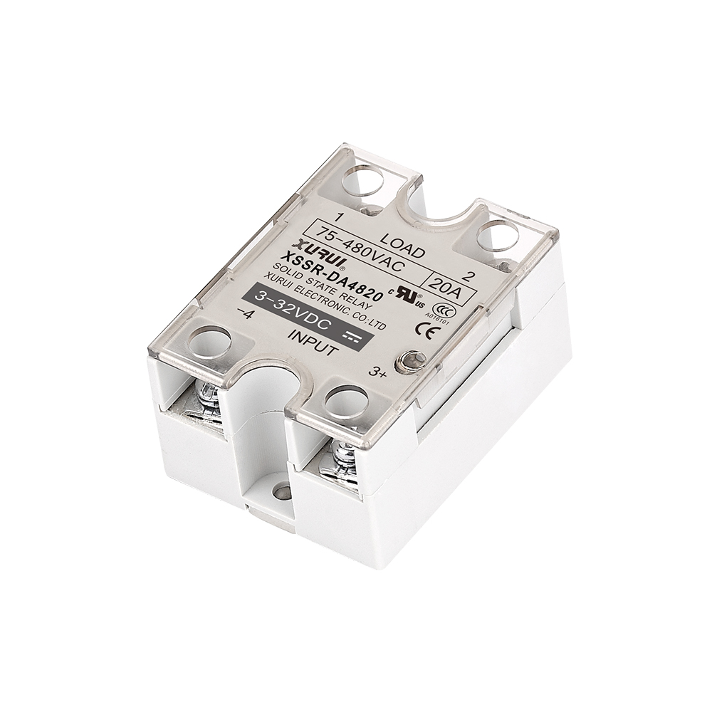
If the panel also uses a solid state relay, follow that model’s input and load diagram; the plug-in relay pinout above does not apply. Send XURUI the SSR’s control voltage, load type and current, and switching duty to discuss an SSR configuration and review the model’s fit.
FAQs
What does terminal 11 mean on a relay?
Terminal 11 commonly identifies the common terminal of the first changeover contact. With the coil off, it connects to 12; when the coil energizes, it connects to 14. It does not identify physical pin 11 unless the socket diagram says so.
Which terminal is positive on a relay coil?
A1 is positive only when a polarized DC coil or its module is marked A1/+ and A2/−. An unmarked, nonpolarized DC coil has no required polarity. Follow the markings when an LED or suppression diode is built in.
What is the difference between 11-14 and 13-14?
11–14 is the common-to-NO path of a changeover contact; 13–14 is a two-terminal NO contact pair. The 11–14 contact may also have an NC path, 11–12. The 13–14 pair does not imply a third terminal or a transfer function.
External Sources
- Omron: Coil Surge Suppression and Reset Time
- Schneider Electric: TeSys LRD Overload Terminals
- Schneider Electric: Auxiliary Contact Block Markings
- Phoenix Contact: Safety Relay Circuit Diagram